October 2012, Vol. 239 No. 10
Features
CP System For Slurry Line With Three-layer Coating In China

This case study describes the design and commissioning of an impressed current cathodic protection (CP) system for a 10-inch OD, 106.2-mile welded steel pipeline with a three-layer coating system. It describes the adventures of cross-cultural technical communications, differences in equipment specifications and understanding and conducting the survey in the lush green mountains of southern China in torrential rains and lightning storms.
The 3,600-psi slurry pipeline, designed by Ausenco PSI (formerly Pipeline Systems Inc.), is the highest operating pressure pipeline in China. The coating system consists of a first coat of fusion bonded epoxy, an intermediate coat and a top coat of polyethylene. The coating is an excellent coating system and less prone to damage during pipe installation as reported in the literature and the manufacturer’s information (ref: Singh, P., “Development of a Cost Effective Powder Coated Multi-Component Coating for Pipelines,” CORROSION/2000, Paper No. 762 (Houston, TX: NACE, 2000)).
The designed CP system consists of three impressed current systems. Each consists of a rectifier unit rated at 230 VAC, 30 V, 24 A DC and a remote surface ground bed consisting of 20 high-silicon, cast-iron anodes. Test stations are installed every 1.24 miles for electrical potential monitoring
It was discovered upon arrival on the site that the installed equipment is significantly different from what was specified and none of the rectifiers were operational due to lighting damage and other faults. Additionally, due to the monsoon season, torrential rains, lighting storms and hilly terrain, the roads were difficult to navigate and access to rectifier sites and test stations proved to be difficult.
A combination of preplanning, technical expertise, luck and very helpful local engineers made it possible to repair the system components and commission the system against all odds in a reasonable time.
The pipeline runs from the first pump station (PS 1), where the pipeline is electrically isolated, utilizing an insulating flange to the Terminal where the pipeline is also electrically insulated (Figure 1). Similarly, the pipeline is electrically insulated at both intermediate pump stations (PS 2 and PS 3). Dual circuit current controlled rectifiers are installed at CP-1 and CP-2 (Figure 2). A single circuit rectifier is installed at CP-3. A remote surface bed is installed at each of the three locations (Figure 3). Potential monitoring test stations were installed every 1.24 miles and a current monitoring (4 Wire) test station was installed every 15.53 miles.
The equipment installed was quite different than what was specified. Instead of a single-circuit manual rectifier unit at each site, dual-circuit automatic current controlled rectifiers were utilized, with all equipment manuals in Chinese. The entire region was in the midst of a severe lightning and rain storm and all of the rectifier units were non-operational, apparently due to lightning damage.
The JDH team had planned to spend two weeks on the commissioning survey and had scheduled another job in nearby Inner Mongolia at the conclusion of this survey. However, due to equipment damage, equipment manuals being in Chinese and several road slides, it seemed fairly impossible to meet our target. We were lucky to have a team of young and enthusiastic local engineers who acted as translators, tour guides and technical personnel. We decided to split our crew into two teams.
Supported by local engineers, equipment vendors and daredevil drivers we managed to repair and commission the equipment, starting from the opposite ends of the pipeline. We were able to swap parts and repair at least one circuit of the dual rectifier in the manual mode. This made the commissioning of the system in time, barely possible. The local engineers and the equipment vendor were very helpful in locating parts to repair the units.
The lesson learned from this equipment failure was that when the general contractor, especially from overseas, calls and tells you that the equipment is installed and the system is ready to be commissioned don’t assume that the contractor is necessarily knowledgeable about the corrosion control system. Try to communicate directly to the installation subcontractor and interview him in detail about the condition of the installed equipment.


Figure 2: Rectifier Unit.

Figure 3: Anode Header Cable on Overhead Poles.
Once all rectifiers were operational, we set them by adjusting the current levels on each, based on our previous experience of three-layer coating systems on long pipelines, and utilizing the NACE criterion of a polarized potential of –0.85 volts vs. a copper sulfate reference electrode. (ref: NACE SP0169-2007, Standard Practice, “Control of External Corrosion on Underground or Submerged Metallic Piping Systems.”)
Testing procedures were generally in accordance with NACE Test Methods. (ref: NACE TM0497-2002, Standard Test Method, “Measurement Technique Related to Criteria for Cathodic Protection on Underground or Submerged Metallic Piping Systems.”) Such coating systems are extremely holiday-free if properly applied and inspected and require a current density of less than 2 micro-amps per square foot. GPS synchronized interrupters were installed in all rectifiers for the measurement of “instant OFF” potentials.
We had planned to use GPS synchronized interrupters to run on 240 volt AC power rather than on batteries, so as to leave them connected for the full duration of the testing program and not to worry about batteries getting drained. These custom built interrupters (Figure 4) worked very well and we were able to keep the synchronized interruption for as long as was required. There were several insulating flanges installed in the system (Figure 5). These were tested utilizing a radio frequency tester and they were found to be well insulated. Two of the major concerns we had during the design of this project were the pipe bridges and the tunnels (Figure 6 and Figure 7).
Figure 4: GPS Interrupter.
Figure 5: Insulating Flange at PS-2.
Figure 6: Pipe Bridge.
Figure 7: Close-interval Survey in Tunnel.
There were numerous bridge crossings in this project. Electrical insulation was maintained between the pipe and the pipe hangers. Since the protection current density was very small, even one shorted or partially shorted insulator could cause a serious drop in pipeline protection in the immediate vicinity. However, all bridges checked out fine. Our concern in the tunnels was possible “shielding” effect in the hills. A close-interval survey was conducted in a few tunnels and it was found that the pipe in the tunnels was well-protected.
Results
During the final days of the survey, a severe lightning storm took out the CP rectifier at PS-3. Both of the circuits of the dual circuit rectifier were damaged. Due to time constraints, weather conditions and other factors, it was not possible to repair the rectifier at PS-3. We readjusted the system based on only two rectifier units approximately 100 miles apart, with amazing results.
Polarized pipe-to-soil potentials were generally in compliance with NACE SP0169-2007. Potential attenuation on such a large span was surprisingly very low, which can be attributed to remote ground beds and the quality of coating. The total current required for the 106.2-mile pipeline was 2.25 amperes. Some of the areas around KM 130+00 were found where the potentials were more positive than the -0.85 mV.
Defective coating was suspected at these locations and subsequently confirmed during a coating evaluation by the owner using aboveground survey techniques, which revealed serious coating defects at this location. (ref: NACE TM 0109-2009, Standard Practice, “Aboveground Survey Techniques for Evaluation of Underground Pipeline Coating Condition.”)
Reportedly, the coating was repaired and it is assumed the pipeline is now well protected and is now maintained by the owner.
Conclusions
The coating system consists of a first coat of fusion bonded epoxy, an intermediate coat and a top coat of polyethylene, which is an excellent coating system that requires less than 2 micro-amps per square foot. However, the coating was damaged during installation, due to extremely rocky terrain and less than adequate coating inspection.
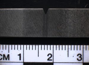
Figure 8: Typical Cross-Country Terrain.
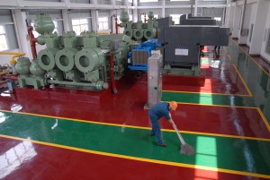
Figure 9: High Pressure PD Pumps.
Do not assume that the general contractor is knowledgeable about the corrosion control system. The installation subcontractor should be contacted and interviewed in detail about the condition of the installed equipment and stage of readiness prior to planning for a survey, especially when long-distance travel is involved.
CP current travels well through mountains and tunnels and the shielding effect is fairly minimal.
Authors
Mohammed Ali, P.E. is with JDH Corrosion Consultants, Inc. in Concord, CA. Contact information: Mali@jdhcorrosion.com, www.jdhcorrosion.com, 925-927-6630 Ext. 122.
Darby Howard Jr., P.E. is with JDH Corrosion Consultants, Inc., Concord, CA.
Raymond B. Clarke, P.E., is with Ausenco PSI, Concord CA.
Acknowledgment
This article is based on a presentation at the NACE CORROSION 2011 Conference & Expo.


Comments