August 2016, Vol. 243, No. 8
Features
Orifice Meter Inspection - An Important but Forgotten Part of Measurement

You attended standards meetings and various measurement schools around the globe and met with your engineering peers to design the most cost-effective meter runs or meter stations. You believe everything is designed as best as it could be. The product is inspected prior to release and acceptance at the fabrication shop, but the Inspection was not thorough enough and the inspector missed key elements of the meter run. This is about to cost you possible millions of dollars in measurement error of up to and possibly over 2.8%. This article lists the measurement effects and ultimate cost of deviating from the specified product. The important takeaway is: Verify Then Trust !
Reynolds Law of Similarity
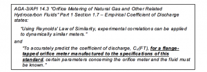
Orifice metering relies on the Reynolds Law of Similarity to predict the meter’s coefficient of discharge and control its measurement accuracy as shown in Figure 1. (Emphasis has been added to highlight the need to ensure that the orifice meter run has been manufactured to the specifications of the standard.)
Figure 1 – AGA-3/API 14.3 Empirical Coefficient of Discharge
For the Law of Similarity to apply, it is a requirement of the inspection process to test and document that the orifice meter run, meter and orifice plate have been “manufactured to the specifications” of the latest edition of AGA-3/API 14.3 “Orifice Metering of Natural Gas and Other Related Hydrocarbon Fluids.”
The interested reader is encouraged to read Michael Reader-Harris’s book[1] “Orifice Plates and Venturi Tubes” for additional information and to gain an understanding of the technical background of this technology.
AGA-3/API 14.3 Parts 1 to 4 – Part 2 Specification and Installation Requirements[2]
This report provides orifice plate and meter tube/fitting specifications, tolerance and installation requirements that are needed to meet AGA-3/API 14.3 Part 1 metering uncertainties. The information provided in this article is not intended to replace the need to follow the recommendation guidance, but is offered to highlight the potential errors associated when meter tubes are not correctly inspected to ensure compliance with the recommendation. It also highlights important differences between the flow conditioner manufacturer’s responsibilities, the meter tube designer’s responsibilities and inspector’s responsibilities, where appropriate.
Location of the Differential Pressure Tap Holes
The location, size and construction of the orifice meter pipe taps can affect the meter’s accuracy.
Figure 2[3] shows the -0.3% to +1.1% possible static pressure error that can occur if the tap holes are beveled or rounded. Estimated errors are in measured pressure associated with the different pressure tap geometries. The left figure is the ideal; the middle figure shows the effect of rounded corners, relative to the ideal. The right figure shows the effect of countersinking relative to the ideal. (Machinists are taught to always bevel or chamfer a hole as an indication of good craftsmanship; not here!)
As the conditions under which these tests were conducted was not published, the effect of rounding or beveling on the orifice tap holes cannot be definitively stated, but indicates that significant rounding or beveling can affect the measurement.
Figure 2 – Error Associated with Rounding or Beveling Pipe Tap Holes
Tap holes should be inspected to ensure that they are square and burr free. Although the standard allows for the tap holes to be “slightly rounded” the intent is not to purposely round the tap hole but to allow for the rounding that will occur during the removal of burrs caused by the drilling process.
The measurement standard also specifies the tap hole size and location. Inspecting the orifice fitting to ensure that the manufacturer meets these size requirements of the standard will control this potential source of this measurement error to less than ~0.1%[4].
Meter Tube Surface Finish
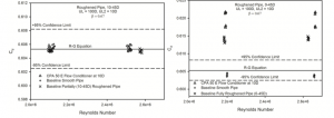
Meter tube surface roughness can significantly affect accuracy. Testing to quantify the effect of pipe roughness that exceeds the allowable limits[5] shows that changing the surface finish from ~50 μinches to ~700 μinches changed the measure volume by ~ 1.5% or more for β=0.75.
Figure 3 – Effect of Changing NPS4 Pipe Roughness From ~ 50 μinches to ~ 700 μinches
Bare Meter Tube Length
Extensive testing to determine the minimum meter run lengths was conducted as part of the AGA-3/API 14.3 Part 2 revision process.[6] To allow the specification of minimum meter run lengths for different conditions, the standard used this test data to identify the minimum length required to limit the installation effect error to < ½ of the RG equation uncertainty (<~0.25%).
It is the responsibility of the measurement practitioner to use this information to specify the meter run lengths required to meet both the minimum requirements of the standard and the measurement facility accuracy. The designer can use this data to identify additional tube lengths required to reduce bias error associated with the meter station design.
It is the responsibility of the inspector to ensure that the fabricated meter run meets both the designer’s and the standard’s minimum length requirements.
Flow Conditioning
Orifice metering research efforts conducted in the 1990s culminated in the last major revision to AGA-3/API 14.3 Part 2 in 2000. The work discovered that the tube bundles specified in the 1991 revision of the standard weren’t as effective at conditioning flow as previously thought[5][7][8]. The standard was modified to recognize the importance of flow conditioning by:
- Incorporating the standard performance test for flow conditioners[9] based on “Reynolds Law of Similarity” developed during the testing process.
- Adding a design specification for the 19 tube uniform concentric tube bundle flow straightener including installation location requirements.
- Classifying all other 19 tube bundle designs as “other flow conditioners” that should be tested to the standard flow conditioner protocol.
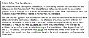
Figure 4 – AGA-3/API 14.3 Part 2 (2000) “Other Flow Conditioners” Requirement.
This approach to including flow conditioners introduced a significant departure from the 1991 edition by including “other flow conditioners” based on a performance criteria instead of prescriptive meter run lengths and tolerance requirements (Figure 4). This change in approach has also led to separating the successful use of flow conditioners into three distinct responsibilities:
- The flow conditioner manufacturer is responsible to:
- Understand the Reynolds Law of Similarity requirements of the flow conditioner design and the manufacturing tolerances required to meet this requirement.
- Conduct performance tests that “confirm the orifice meter diameter ratio (β) meter tube length, and flow conditioner location for which acceptable performance is obtainable” and provide proof of those test results to the purchaser of the flow conditioner.
- Conduct quality control testing of the manufactured flow conditioners.
- The measurement practitioner designing the meter tube is responsible to:
- Select and specify the flow conditioner based on the flow conditioners’ performance tests and the meter tube acceptable performance requirements.
- Specify the meter tube lengths and flow conditioner location based on the metering installation layout and the specified flow conditioner installation requirements.
- The meter tube inspector is responsible to:
- Verify that the specified flow conditioner has been delivered. This includes verification of the manufacturer as they are responsible for the flow conditioners’ quality control testing.
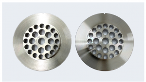
For example, as an inspector you may not see a difference in these two flow conditioners indicated in Figure 5 – Two very different flow conditioners look the same, from the end of the meter tube, but the manufacturer inspection process does. Yes they both have 25 holes, but upon further research the holes are not sized the same. Would you have caught this?
Figure 5 – Two very different flow conditioners look the same
- Verify that the flow conditioner has been installed in the correct meter tube location and that the meter tube length meets the specified design requirements.
But what is the effect of using substitute flow conditioners? Aren’t they just plates with a hole pattern? (That is a similar thought to – Why not just use a tube bundle flow conditioner?)
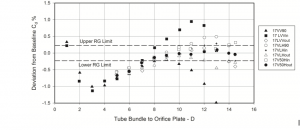
Figure 6 (Figure D29 from the API White Paper[10]) shows the tested performance of a 19 tube bundle flow straighter downstream of a partially closed valve. No location of the tube bundle meets the 0% additional uncertainty, and bias error of up to 1% can be expected if a tube bundle was used under these circumstances.
Figure 6 – 19 Tube Bundle Flow Straighter Downstream of Partially Closed Valve – 0.67 Beta ratio
Important Takeaway: Obtaining a dimensional tolerance form or certificate from the fabricator indicating that the flow conditioner meets all the requirements of the applicable standards does not guarantee that the flow conditioner provided meets the requirements and performance of the flow conditioner specified by engineering. Because it is the manufacturer’s responsibility to conduct the manufacturing quality control, it is the inspector’s responsibility to verify that the specified manufacturer’s flow conditioner has been provided and that the manufacturer’s quality control documentation matches the manufacturer and serial number marked on the flow conditioner.
Requirements Meter Tube Diameter, Roundness and Fabrication
Because these measurements are part of the fundamental “Reynolds Law of Similarity” requirements, testing of deviation from the standard specifications has been limited to testing that confirms the specified conditions provide adequate controls.
It is the responsibility of the inspector to ensure that the meter tubes meet both the designer’s specified meter lengths as well as the standard specified pipe length. The inspector is also responsible to inspect the meter run for:
- size and roundness by measuring the pipe at the specified locations, recording the meter run temperature at which the measurements were made and confirming that the measurements meet specified tolerances,
- shoulders, offsets, ridges, welding seams, and the like that should not exist,
- straightness,
- orifice plate gasket or sealing device recesses and protrusions,
- thermal well location,
- confirmation that there is no orifice tap communication or leakage and no holding or sealing device fluid bypass, and
- that there are no pipe connections within the specified upstream and downstream meter tube sections other than orifice flange taps.
Conclusion
Successful inspection requires three things from the inspection process:
- Verification and documentation that the meter run conforms to the AGA-3/API 14.3 Part 2 – Specification and Installation Requirements.
- Verification that the meter run has been manufactured to the measurement practitioner design requirements for pipe lengths and material specifications.
- Verification that material that is specified by manufacturer make and model has been correctly supplied and that the serial number of the delivered product and the manufacturer’s quality control documentation match.
Successful verification that the meter run has been manufactured as designed, that conforms to the standard requirements and use the material specified will result in a product that can be trusted.
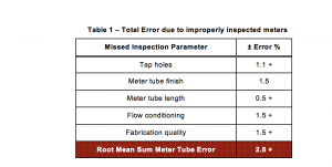
Table 1 – Total Error due to improperly inspected meters says it all. If one were to inadvertently miss every parameter listed in this article, you would be installing a meter tube of almost no value to you. Yet, you are assuming and communicating to your customers that a proper AGA-3 meter tube has been procured, inspected and installed. Major errors – all due to lax inspections.
[1] W. Studzinski, U. Karnik, P. LaNasa, T. Morrow, D. Goodson, Z. Husain, J. Gallagher – “White paper on orifice meter installation configurations with and without flow conditioners.” prepared for API 14.3 Part 2 and published as Gas Research Institute Report GRI 99/0262
[2] T.B. Morrow – “Orifice Meter Installation Effects In The GRI MRF” presented at the 3rd International Symposium of Fluid Flow Measurement, San Antonio TX, March 1995.
[3] P. LaNasa – “A Review Of API MPMS 14.3/AGA Report No. 3 – Part 2” presented at the American School of Gas Measurement Technology 2012.
[4] M. Reader-Harris – “Orifice Plates and Venturi Tubes” published by Springer Cham Heidelberg New York Dordrecht London (Section 2.3.2.2 Flange and D and D/2 Tappings)
[5] T. B. Morrow, D. L. George, M. G. Nored – GRI Topical Report GRI-00/0141 “Operational Factors That Affect Orifice Meter Accuracy”
[6] W. Studzinski, U. Karnik, P. LaNasa, T. Morrow, D. Goodson, Z. Husain, J. Gallagher – “White paper on orifice meter installation configurations with and without flow conditioners.” prepared for API 14.3 Part 2 and published as Gas Research Institute Report GRI 99/0262
[7] T.B. Morrow – “Orifice Meter Installation Effects In The GRI MRF” presented at the 3rd International Symposium of Fluid Flow Measurement, San Antonio TX, March 1995.
[8] P. LaNasa – “A Review Of API MPMS 14.3/AGA Report No. 3 – Part 2” presented at the American School of Gas Measurement Technology 2012.
[9] T.B. Morrow – GRI Topical Report GRI-97/0207 “Development of a Flow Conditioner Performance Test.”
[10] W. Studzinski, U. Karnik, P. LaNasa, T. Morrow, D. Goodson, Z. Husain, J. Gallagher – “White paper on orifice meter installation configurations with and without flow conditioners.” prepared for API 14.3 Part 2 and published as Gas Research Institute Report GRI 99/0262





Comments