July 2016, Vol. 243, No. 7
Features
Different Perspective on Custody Transfer Measurement
Custody transfer measurement in the petroleum industry has been described many ways. It’s been called “an accuracy in measurement both the buyers and sellers can agree upon,” or sometimes described as “the best that can be achieved to meet the contract conditions.” There are many other descriptions as well. But in reality it is simply “the search for the truth.”
Ever since liquids have been bought and sold, people have searched for better ways to measure volume on the fly with increased accuracy. A big advancement for liquid measurement in the petroleum industry was the pipe prover. For a bidirectional pipe prover, API requires a repeatability on the prover volume at water draw of 0.02%. This is in comparison to a standard such as NIST traceable Seraphin Cans.
If we want to put 0.02% into perspective that is 6.45 teaspoons or a little more than 2 tablespoons of liquid in one 42-gallon barrel. That is good measurement and a worst-case scenario. But we all strive to exceed the 0.02% required by API because we know and understand the value of increased accuracy. This better accuracy is achieved by the Patented SCS Prover®.
A good example of a “time-honored tradition” is saying we are using a meter rover to prove the meter. In reality what we are doing is proving the measurement system. We compare the standard volume of the prover corrected by the prover temperature, pressure and density to the standard volume measured by the meter corrected for temperature, pressure, density and the calculations used to produce these numbers. What we are doing is “proving the measurement system.” But we do not call it that? No, but we should.
Then there are times when we are trying to solve a problem, but we are controlled by company and industry standards, and, of course, the “This is how we have always done it” rule. Still, sometimes when we are faced with a problem we need to solve it outside these conventions. An example of this is what occurred during development of the straight calibrated section bidirectional pipe prover.
Welker Flow Measurement Systems (WMFS) found that by making the calibrated section straight, tipping the horizontal launchers, sizing the launchers properly and placing the pressure and temperature transmitters correctly, workers were able to greatly improve the repeatability and serviceability of the conventional bidirectional pipe prover.
Process conditions for both the pressure and temperature transmitters should be considered thoroughly. Are they needed on the inlet and outlet of a prover when the inlet transmitter is close to the meter transmitter? Is the error caused by the transmitter’s error band greater than the possible difference caused by using only one transmitter?
The pressure drop from the meter transmitter to the inlet of the prover needs to be calculated. If it is lower than the possible difference in two transmitters then only one transmitter can be used. For example, it takes about 25 feet of pipe at full flow on an 8-inch pipe to cause a pressure drop of 0.3 psi, which is within the two transmitters’ possible difference.
Transmitter Specifications
The possible difference in two temperature transmitters could be 0.52o F. Under typical conditions it would take over 200 feet of pipe to cause a temperature drop of 0.26o F. Would it be advisable to use two transmitters if the distance of the pipe between the transmitters is less than 100 feet? Probably not.
Finding good, true elbows to go in the calibrated section, especially in the larger sizes, is difficult. To avoid this problem WMFS designed a prover with a straight calibrated section with the elbows in the pre-run. This improved repeatability and led to other improvements like eliminating machined flanges, making maintenance easier and easing the ability to tip the launchers.
There are no alignment flanges in the calibrated section. Alignment flanges are expensive and machining on the flange or installing pins reduces the integrity of the alignment flange and, therefore, the piping system. Flanges in the pre-run are aligned using shoulder bolts that are about the same diameter as the flange bolt holes. Not having to cut or drill a flange is a safety improvement.
There are no elbows in the calibrated section. Elbows cause a pressure and flow change as the ball moves through the elbow, and there can be loss of fluid if the elbow is not perfectly formed in the inside diameter. Because the ball doesn’t have to go through elbows as it passes from switch to switch, less inflation of the ball is required, making for better water draws and better proves with less pressure drop.
The calibrated section can be rolled out and inspected without another water draw because no flanges are broken in the calibrated section. This is a cost savings both in time and water draw cost.
It is ideal for Coriolis and ultrasonic liquid meters with manufactured pulses because the flow before and in the calibrated section is not disrupted by the ball passing through elbows, welds or flange sets. Because the ball can be inflated less, it passes smoothly between the detectors, not disturbing the flow.
Since the flow through the calibrated section is smooth, the pulses from conventional PD and turbines will be more evenly spaced, giving better results, especially when pulse interpolation is used.
The sphere in a SCS prover does not have to be over-inflated to compensate for irregularities in elbows and flanges. The higher inflation of the sphere, the higher the drag on the pipe walls, which increases wear on the sphere.
Water draw repeatability of 0.005% is common with the straight calibrated section prover. This, of course, also reduces overall uncertainty.
Better Reliability
Wear and tear on equipment is caused by the stress put on the equipment – less stress, less wear. Reducing the drag on the prover sphere as it moves through the prover reduces the wear on the ball and the coating inside the prover. That means longer ball life and longer prover barrel life, requiring less maintenance and repair.
There are several manufacturers of sphere detector switches, all of which are very good. The API Manual of Petroleum Standards, Chapter 4, “Proving Systems Section 2 – Displacement Provers Appendix A” gives a mathematical explanation of sphere position repeatability. Naturally the rounder the ball the more precise the detector contact will be. Detector switches are normally repeatable to within 0.002 inch. However, the repeatability of the switches and the required volume are not the only things that affect the calibrated volume of the calibrated section.
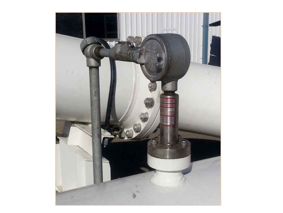
Fluid leaking around the detector switch opening is one. There has been discussion about the prover sphere’s ability to seal off the opening that the detector switch sticks through as the sphere passes underneath. If the ball does not seal off the opening, fluid will bypass the opening and the prover will lose repeatability, or it may not prove at all.
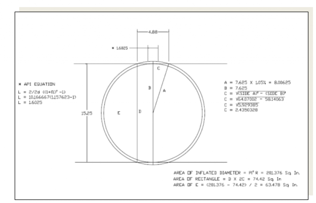
Since the sphere in an SCS prover is inflated less than a sphere in a conventional prover, there must be a way to prove the inflation will create enough sphere to calibrated contact length to seal off the detector switch opening.
By reducing inflation on the sphere, the spheres will be rounder, last longer and the prover will not have to be opened to replace or check the sphere as often. Building the launchers so the spheres are not damaged when they enter the launchers also reduces the number of times the prover needs to be opened to replace a damaged sphere.
The less the sphere has to be inflated, the less likely the sphere has to distort or wear as it moves through the pipe. And, of course, it causes less drop in pressure. It takes about 80 psi to inflate a 30-inch sphere to 3% oversize. If the same sphere is inflated to 1%, only 30 psi is required. Less pressure in the sphere means less stress on the ball and less friction as the sphere passes through the prover pipe. Friction between the sphere and the pipe causes wear. One percent over size provides more than a 4-inch-wide contact area on the pipe, using a 30-inch sphere. Less inflation reduces the drag on the ball, so less pressure is required to move the ball smoothly in the prover pipe.
Procedure to determine the sphere contact length to ensure sealing
To go forward, we need to know if the sphere seals off as it passes under the detector switch opening. Fortunately, this is easy to determine at water draw. Before a water draw we can follow procedures to ensure there is no leakage around the sphere at the detector switch opening.
We need to know the exact diameter of the detector switch opening. It must be drilled, not torch cut. Normally the detector switch hole is 0.875 inch or 7/8 inch.
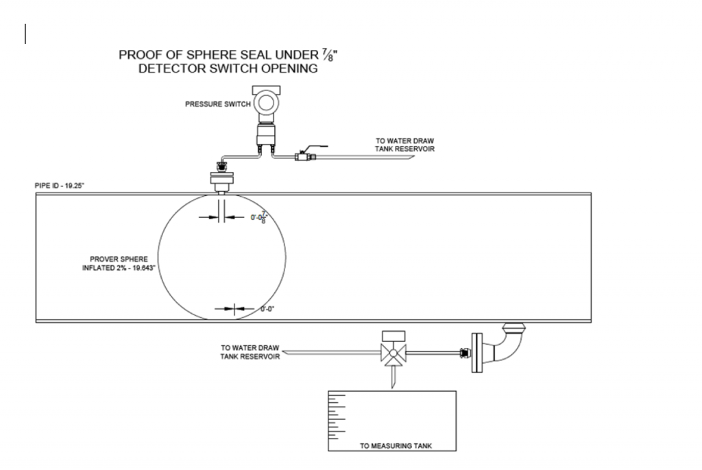
Place a pressure switch in the line between the calibrated section and the drain valve. Set the pump used to circulate the sphere at water draw to 20-25 gpm by pinching down on the discharge that runs back into the return tank. This equalizes the pressure on both sides of the sphere and in the drain. Open the drain to let out about 10 gpm so pressure will be held upstream of the switch to keep it in position. Forty gpm is going into the drain on the water draw trailer and about 10 gpm is coming out the drain.
When the sphere passes over the entire drain hole, the drain is shut off, pressure drops on the pressure switch and the switch directs the flow into a water draw or another clean can via the three-way solenoid. When the ball starts to move past the drain hole, the pressure on the switch goes up and the switch changes position. The solenoid switches and water stops running into the clean can.
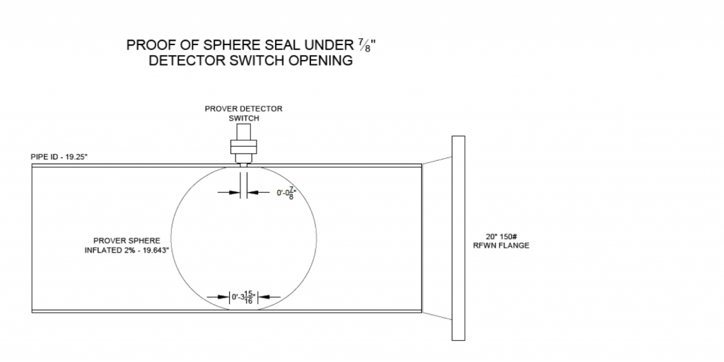
The water in the can is measured to determine volume. This volume, converted to length in the ID of the prover, plus the diameter of the detector switch opening, (think about it), is the contact length of the sphere. You can do this test with any prover.
This test not only determines the sphere contact length but also verifies that the detector switch hole is completely covered and there is a seal over the detector switch hole as the sphere passes underneath the detector switch.
For a quick way to verify the sphere seals off the Detector Switch Opening, fill the prover with water and launch the sphere but do not run it all the way to the detector.
Remove the first switch and move the sphere toward the switch opening. When the sphere is under the detector switch plunger opening hole, the flow will be shut off and there will be no more flow. This is proof that the switch hole is covered. If water continues to flow when the ball is under the switch plunger opening, the sphere needs more inflation. Care must be taken to not add too much pressure to the sphere seal area. Only enough pressure to move the sphere is needed, similar to the pressure required to move the sphere during a water draw.
Launching Chambers
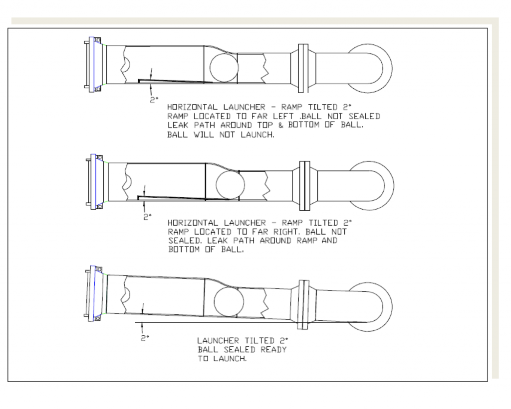
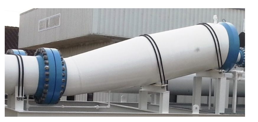
Sphere-launching chambers can be either horizontal or vertical. Each has advantages and disadvantages. The vertical launchers made the sphere difficult to install and remove. A huge disadvantage of a horizontal launching chamber is the ramp in the launchers keeping the sphere close to the prover pipe so it will launch. It also has to be perfectly horizontal so that no air is trapped on one end of the launcher. And the prover has to be completely drained for sphere removal and maintenance. By tipping the entire launching chamber minimum 2 degrees, the angle of a typical ramp, these disadvantages are avoided.
The rule of thumb for prover launchers has been two pipe sizes larger than the calibrated section. This works up to about a 16- or 20-inch prover. After that, the velocity around the sphere gets too high and the sphere and or ball stopper will be damaged by the high velocity in the launcher, causing the sphere to slam against the bars or ball stopper.
Proper sizing of the launching chambers is critical. If the launcher diameter is too small the sphere is carried along with the fluid as it moves rapidly in the launching chambers. The “two pipe sizes larger” rule of thumb works on the smaller 6-, 8- and 10-inch provers with 10-, 12- and 14- or 16-inch launchers, but not on larger sizes.
What is interesting is that at full flow on the smaller sizes in which the velocity through the prover pipe is 5 feet/second, the velocity of the liquid around the sphere in the launching chamber is also around 5 feet/second. On larger provers the velocity of the fluid around the sphere can go to over 20 feet/second using the two diameters larger rule.
From experiments using clear pipe at WFMS we have found the sphere is not as aggressive at under 5 feet/second. There is no problem with sphere damage even on larger sizes following this 5 feet/second rule. This can be adjusted for fluids having a higher viscosity.
Reducer on Launchers
Installing reducers on launchers where the piping from the four-way is attached increases the pipe size into and out of the launchers and lowers the pressure drop caused by the bars or other protection placed in the launchers to keep the ball from being pulled into the four-way piping.
When forged eccentric reducers are used, there is no problem with the sphere launching when the launchers are tipped. Forged reducers are used on the SCS prover up to a calibrated section size of 16 inches; above that, it is more economical to use a fabricated rolled reducer. By making the reducer concentric and longer, the tipped launcher has the ease of serviceability of a horizontal launcher and the sphere-launching ability of a vertical launcher.
A field prove report from a Coriolis meter system flowing full flow.
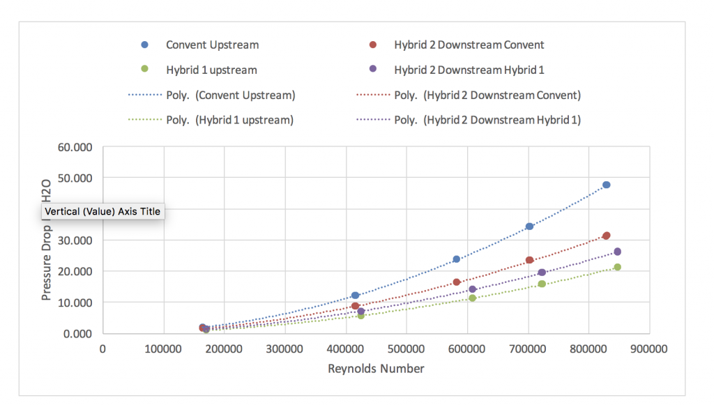
High-pressure drop across a strainer in any application is a problem. Incorrect design can cause a high-pressure drop and require frequent cleanings.
Mesh screen has always been a better strainer basket material for lower pressure drops, but the screen lacked structural strength. Strainer baskets of only mesh are easily damaged. Rolled perforated plate has much more strength but causes more pressure drop due to the upto 60% flat surface. Since the most important part of a strainer basket is the “target” area, WFMS made the target area mesh, and the rest of the basket perforated plate.





Comments