
May 2024, Vol. 251, No. 5
Features
Navigating Small Diameter ILI Challenges in Crude Oil Gathering Systems
By Frank Micheli, Bridger Pipeline, Casper, Wyoming, and Kenneth Maxfield and Phil Tisovec, KMAX Inspection, Salt Lake City, Utah
(P&GJ) — Bridger Pipeline operates a crude oil gathering system, of approximately 3,500 miles, in the Williston Basin of western North Dakota, eastern Montana and the Powder River Basin of Wyoming. The system contains many small-diameter (3-inch to 6-inch) gathering lines that are a challenge to inspect with ILI tools.
These challenges include low-flow conditions, line cleanliness and paraffin build up. Many are first time inspections of pipelines with limited or unknown records, trap configurations, and fittings such as heavy wall tees and elbows. Also of concern are weather constraints with the seasonality of ILI inspection projects for pipeline repair and access.
This article presents how these challenges are addressed to successfully run ILI to comply with Bridger’s integrity management program.
Bridger has taken a proactive approach to its pipeline integrity program by inspecting with ILI tools all segments on a regular basis. The integrity philosophy is, “a leak is a leak.”
The goal is to identify and minimize risks within the entire system. There are many factors which pose potential threats to its unregulated gathering lines. Bridger wants to be proactive in combating those threats to reduce the probability of a leak as much as possible.
Some of the issues that could be potential threats include:
- Third-party line strikes from excessive activity in pipeline areas
- internal corrosion caused by slowing production, which makes cleaning more challenging including the potential for water and chemicals contamination from producing wells
- external corrosion
- unknown pipeline characteristics from historical acquisitions.
ILI Pigging Program
Bridger primarily uses axial MFL tools to inspect the system, but occasionally uses circumferential MFL and UT tools when their risk analysis indicates that there is a need. What follows is what a typical year of the ILI pigging program looks like for Bridger.
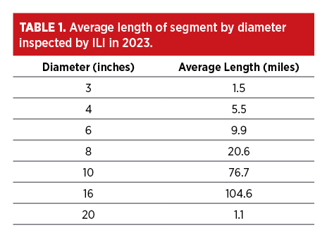
In 2023, the company inspected all segments with MFL ILI tools. Of these segments inspected, only 20% are regulated. Notably, 30% of the segments were first time inspections with an ILI tool. Figure 1 shows a chart with the segments grouped by diameter. Note that over 75% of the segments are smaller diameter (3-inch, 4-inch and 6-inch) segments.
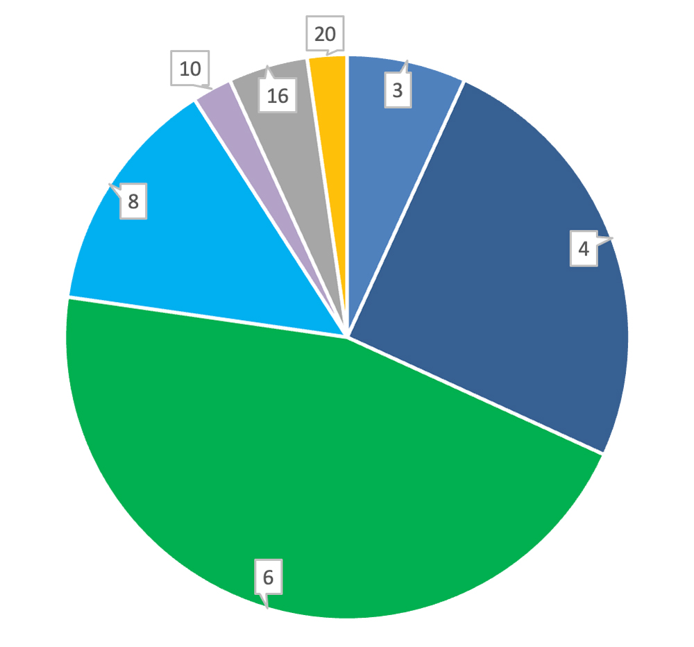
The length of segments inspected in 2023 vary from 1 mile to 105 miles.
Table 1 shows the diameter of the segments inspected and the average length of the segments. Typically, the length of the pipeline segment goes up with the diameter of the pipe.
In 2023 alone, Bridger performed 210 excavations to evaluate anomalies called out by ILI tools. Bridger completes at least one verification dig on each segment it inspects with an ILI tool.
Challenges of ILI
Running ILI tools in the Bridger system can be challenging due to assorted reasons discussed in the following sections.
Weather
Due to the geographic location of the Bridger system in the Williston Basin of western North Dakota, eastern Montana, and the Powder River Basin of Wyoming, the weather conditions can vary tremendously over the year.
Winters in this part of the USA can be brutal with deep snow, cold temperatures, and high winds. In the spring when the snow melts, mud can make pipeline access difficult if not impossible. Snowstorms can be present even into the month of May (Figure 2).

The weather creates a practical cycle to the ILI program. ILI tools are run in the spring to late summer, so that the results of the ILI inspections are received in time to perform pipeline digs and repairs before winter sets in the late fall.
Pipe Records
The pipeline system contains pipeline segments that can be old or recently installed, including segments acquired by acquisition. Pipeline records for some of these segments are often missing information or contradictory, especially segments that have never been inspected by an ILI tool.
In 2023, 13 of the 44 total inspected pipeline segments were first time ILI runs. Often there are no records, or incomplete records of these pipeline segments. It can be challenging to run an ILI tool in a pipeline segment without a confident knowledge of wall thicknesses, bend radius, and pipeline fittings.
These unknowns are even more challenging in smaller diameter pipe segments where the probability of sticking an ILI tool in these segments increases versus larger pipelines [1].
Configuring for ILI
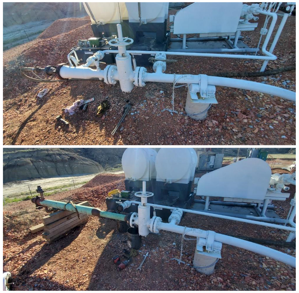
Running ILI tools in pipeline segments requires that launchers and receivers are long enough to accommodate ILI tools. Most of the Bridger system’s lines do not have permanent traps with sufficient length for ILI tools. Temporary traps or extensions are installed on most of the segments that are inspected with ILI tools. Figure 3 shows before and after installation of a temporary trap extension.
Line Cleanliness
Cleaning lines prior to running an ILI tool is important to ensure the ILI tool can get good sensor readings from the inside surface of the pipeline. Most cleaning is done by running cleaning pigs through the pipeline segment weeks and days before the ILI inspection.
This can be challenging because some of the pipeline segments do not flow continuously due to low production of the wells feeding the pipeline segment.
Ferrous Debris
If the pipeline segment has not been previously inspected, there is risk that the pipeline segment can contain a lot of ferrous debris. This ferrous debris could have been present in the pipeline since it was constructed or be a byproduct of internal corrosion present in the pipeline segment.
Running a cleaning pig with a magnet can remove this ferrous debris. If there are substantial amounts of ferrous debris, multiple passes of a cleaning pig with a magnet could be required.
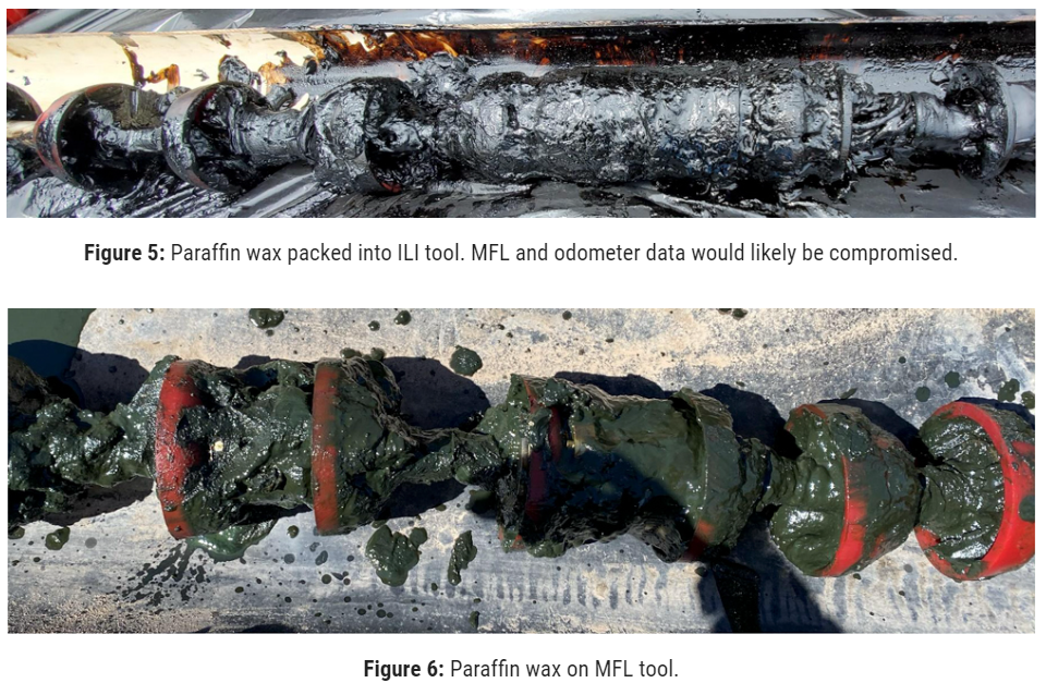
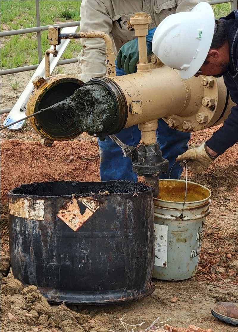
Paraffin Wax
Paraffin wax is the number one concern with running an ILI tool in the Bridger system. Crude oil is a complex organic mixture containing hydrocarbons and a few non-hydrocarbon materials.
The general composition of crude oil is categorized into saturates, aromatics, resins, and asphaltenes [2]. Some of the saturate compounds have high melting points and can solidify at low temperatures. They precipitate out of the fluid to a certain degree as the temperature drops, typically below 80° C, to form colloids known as wax.
The wax-forming molecules are mainly normal and branched alkanes though some naphthenes attached to long carbon chains are also possible wax-forming molecules [3]. As the temperature of the crude oil lowers, wax starts to deposit as a layer along the pipe wall.
Not all wax is deposited on the pipe wall, as some of the wax remains suspended in the crude oil flowing down the pipeline. Studies have shown that wax deposition is mainly dependent on temperature and oil composition [4].
Paraffin wax can be removed from the pipeline using cleaning pigs, chemicals, heated fluid flowing through the pipeline, or a combination of these. Running cleaning pigs through the pipeline is the most economical way to remove paraffin wax from the pipeline. Multiple passes of cleaning pigs are often required to remove the wax from the pipeline. Bridger uses cleaning pigs almost exclusively to remove paraffin from its pipeline system.
Paraffin wax can create two main problems with MFL ILI: tool sensor response and odometer function. When MFL sensors do not ride directly on the pipe wall, the sensitivity to detect changes in the magnetic field caused by metal loss, especially for small metal loss features, decreases. The usually stable background magnetic field level detected by the sensor also changes as the distance from the pipe wall varies. This variation seen by the sensor can create errors in sizing metal loss anomalies. As a result, paraffin wax can cause the probability of detection to decrease and the sizing error of metal loss anomalies to increase.
Additionally, paraffin can pack into and around the odometers which are responsible for recording overall line distance and, therefore critical to anomaly and feature locating.
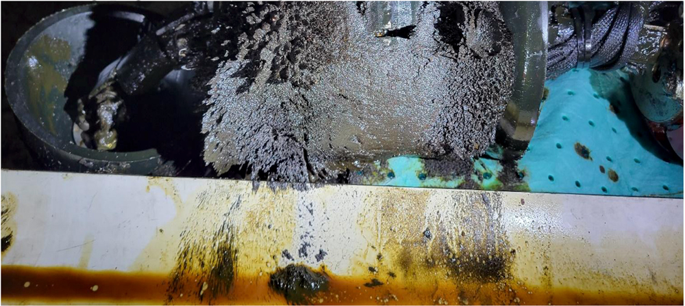
Figures 5 to 7 show some of the paraffin wax issues that can be encountered when running ILI tools.
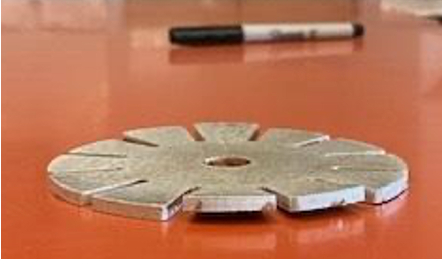
Gauge Pig
Bridger runs a gauge plate pig through all lines prior to running an ILI tool. Running a gauge pig through the pipeline segment helps prove ILI tool compatibility and increases the probability of getting a good ILI inspection without sticking an ILI tool in the pipeline segment.
If there is no damage to the gauge plate after running a gauge pig, there is a good chance that the ILI tool can pass through the pipeline segment with no issues. If there is damage to the gauge plate, then a deformation (caliper) tool could be run through the line to look for geometric features or restrictions that could cause issues with running an MFL tool through the line.
Figure 8 shows a gauge plate pig configured in combination with a cleaning (brush) pig after running through the pipeline segment.
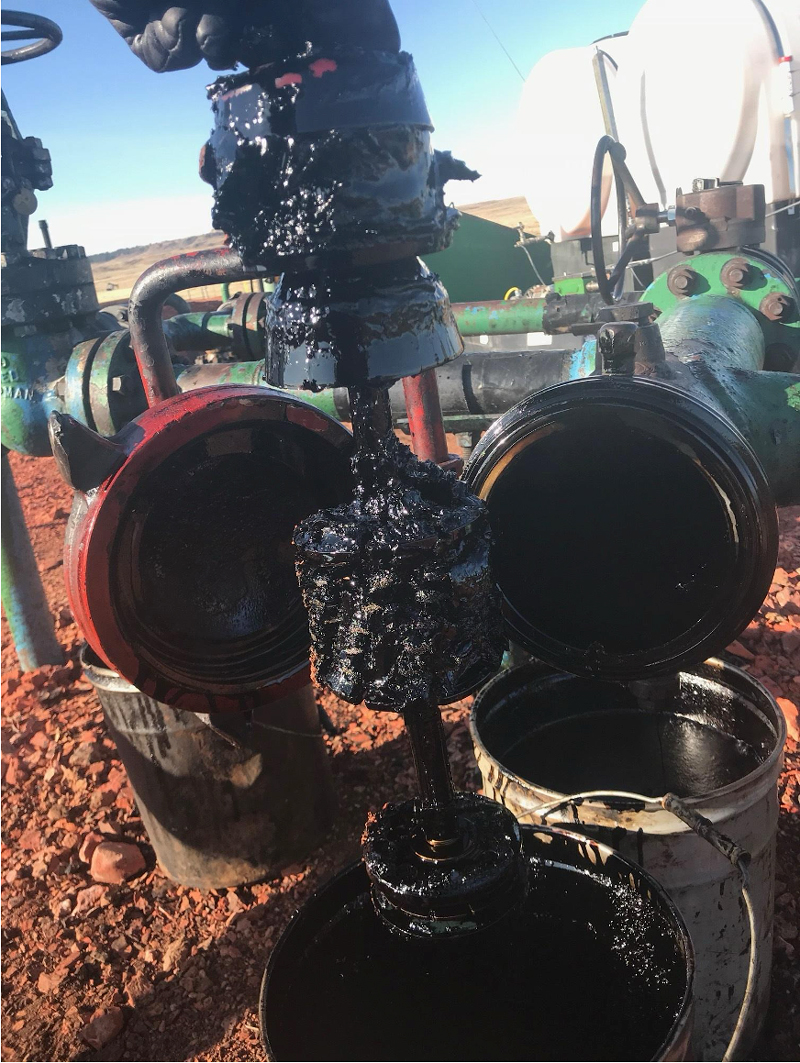
Figure 9 shows an example of a gauge pig plate post run with slight bends on two of the tabs indicating some type of intrusion or bore reduction.
Tool Configuration
The ILI tool configuration is determined by using previous ILI inspection data from the segment if it is available. The length of the ILI tool drive and MFL magnetizer sections can be optimized for the best performance while still passing through the pipeline segment without issue.
If the pipeline segment has not been inspected by an ILI tool, then the configuration of the ILI tool must be more conservative to allow for unknown fittings and elbows that might cause the ILI tool to stick in the pipeline segment. If the pipeline segment has never been inspected with an ILI tool, Bridger assumes there could be 1.5D elbows in the segment and the ILI tool is configured to be able to pass a 1.5D elbow.
Operational Parameters
Some of the segments inspected by Bridger do not have adequate pressure or flow to propel an ILI tool through the segment to be inspected. This is more prevalent in the small-diameter lines that are fed by wells that have low output, or a low-pressure pump.
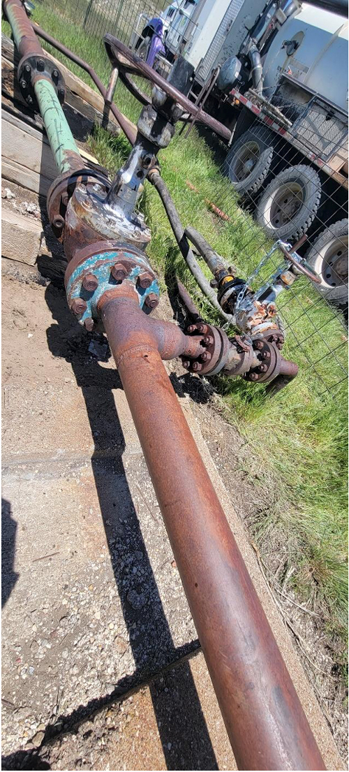
In this situation, a pumper truck is used to bring in product, and provide the necessary pressure and flow velocity to move the ILI tool through the pipeline segment. Figure 10 shows a pumper truck connected to the launch piping which provides adequate pressure and flow to run an ILI tool.
Odometer, Mapping
Paraffin wax buildup is a constant issue with getting adequate data from ILI tools run on each segment. The amount of paraffin varies dramatically from segment to segment. The smaller the diameter and lower flow of the pipe, the more paraffin becomes a problem with the ILI inspections.
Paraffin can degrade MFL and caliper data, but it can also cause the tool’s odometers which track linear distance to stick or slip. For inertial measurement unit (IMU or mapping) runs, the odometers are a critical input to enable calculation of spatial center line data.
The spatial IMU data is important to Bridger both for locating potential dig sites as well as investigating integrity factors such as low (elevation) areas of lines where internal corrosion is more likely. Bridger commonly had to rerun tools due to odometer issues caused by paraffin in their 3-inch, 4-inch and 6-inch lines.
KMAX Inspection, the vendor for most of Bridger’s smaller diameter lines, has developed proprietary methods to reconstruct odometer distances using available datasets recorded by the tool as well as geospatial data. This allows KMAX Inspection to still provide accurate linear distance and spatial mapping data for the pipeline segment, even when there were odometer issues during the run.
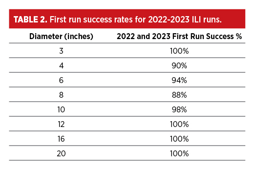
ILI Success
Bridger tracks when an ILI tool is successfully run through a pipe segment for the first time. Table 2 shows the first run success of running ILI tools in 2022 and 2023.
Bridger has also decided to perform a verification dig on every segment inspected by ILI where practical. This allows Bridger to understand the performance of the ILI tool as well as repair the segments as needed.
In 2023, Bridger evaluated 210 areas in their system. Bridger locates these areas using IMU mapping data provided by its ILI vendors, even down to the 3-inch segments. Bridger evaluates the data collected and compares the results to the ILI vendor’s tool specifications to validate tool performance.
Examples of Challenges
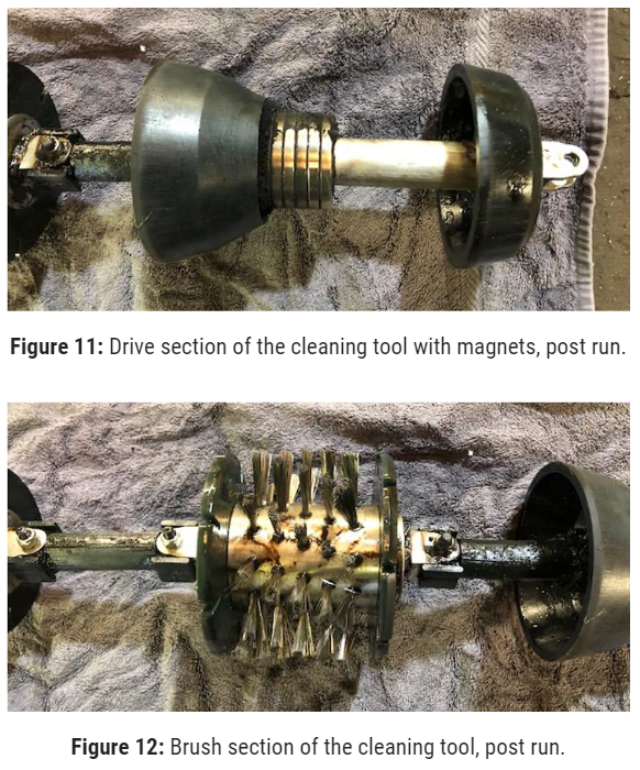
Tee used as an elbow: Bridger was preparing to inspect a 4-inch line with an MFL ILI tool for the first time. Prior to running an MFL/deformation/IMU combo tool, a single combined gauge plate and cleaning pig tool configured by the ILI vendor, KMAX Inspection, was run in the pipeline.
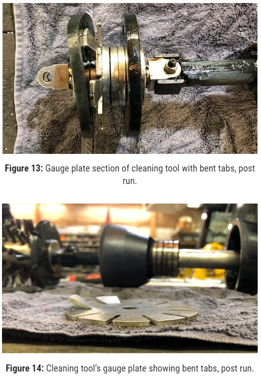
The gauge/cleaning pig was launched and received in the pipeline segment with no apparent issues. Figures 11-13 show the condition of the gauge/cleaning pig after being run through the pipeline. The gauge plate had two tabs slightly bent (Figure 14).
After a discussion with KMAX Inspection, it was decided that although the gauge plate had bent tabs, that the bore of the pipe should be able to pass the KMAX Inspection MFL combo tool.
It is common to see single bent tabs caused by intrusions such as pig signallers (pig sigs) installed in the pipeline, even though the overall bore of the pipe is acceptable for ILI tool passage.
When the MFL combo ILI tool was run through the pipeline, the tool became stuck, and product was bypassing the ILI tool. The location of the ILI tool was determined by first locating the last above ground marker (AGM) location the tool passed.
Then using a handheld location device that detects the 22 Hz frequency transmitter on the ILI tool, a technician walked along the pipeline right of way and was able to locate the tool.
The pipeline was excavated at this location which is shown in Figure 15, and it was determined that a tee fitting was functioning as a 90-degree elbow. The ILI tool was of course not able to navigate through the tee from this direction and became lodged there. The line segment had to be drained and the ILI tool cut out from this location.
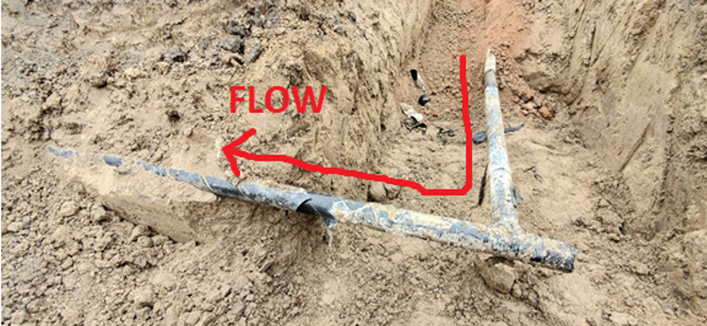
There are some lessons to be learned from this situation. At some point in time this pipeline was modified by either cutting the line and plugging the abandoned end of the tee or they simply used a tee where a 90-degree elbow was needed.
The crew doing the modification should have been aware of general pipeline piggability and should have never substituted a tee as an elbow. Also of note, when running a gauge pig through a pipeline, the results are not always black and white. Various “shades of grey” exist where calculated risk might need to be made with running an ILI tool, running a geometry/deformation ILI tool or other approaches to further investigate ILI tool passage.
If the choice would have been to run a geometry/deformation tool in this case, the same result would have occurred with an ILI tool being stuck in the pipeline at the same location.
Pipeline installed inside another pipeline: Many years ago, Bridger abandoned a 1-mile, 6-inch pipeline segment. A new pipeline was needed to replace the abandoned line, so it was decided to use the 6-inch abandoned pipe as a housing for a new 4-inch pipeline. The 4-inch pipe was strung and pulled through the inside of the 6-inch pipe, meaning no excavation was used to install the new line. Figures 16 and Figure 17 show where the new 4-inch line exits from inside the 6-inch line.
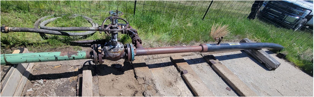
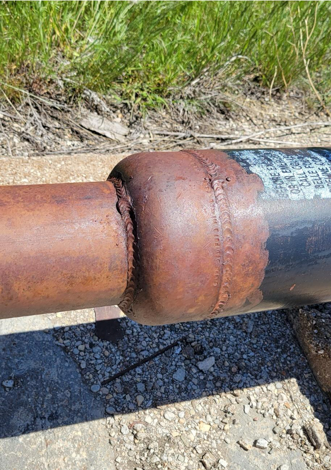
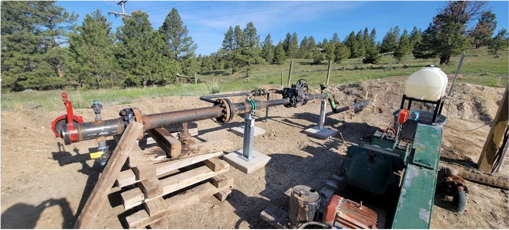
Figure 18 shows the 4-inch launcher and the pipe entering the ground. Notice the pipeline goes up a hill right after the launcher. This configuration causes a low spot in the pipeline right where the piping enters the ground.
After a KMAX Inspection ILI tool was run and the data was analyzed, it was discovered that some significant internal corrosion was occurring at this low spot in the pipeline. Figure 19 shows the ILI data at this low spot and the corresponding internal corrosion. At the right (downstream) side of the data, two dents and the begin of the outer 6-inch abandoned pipe can be seen.
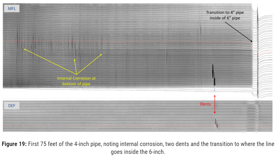
Below are the summary of results and conclusions from the KMAX Inspection ILI run on this unique line:
- The total line inspected was 5,658 feet (1.07 miles) in length, with 5,578 feet of pipe inside of the abandoned 6-inch line.
- There were 124 metal loss anomalies/clusters detected with the deepest reported as 54% of wall loss.
- There were 20 dents detected ranging from 1.0% to 5.7% depth of OD. This could be considered a high number of dents for just over 1 mile of new pipe. It is assumed that the pipe was dented during the installation process of the 4-inch pipe being pulled into the 6-inch pipe.
Dual-Diameter Line
Bridger operates a 4-inch/6-inch, dual-diameter pipeline segment that had never been inspected with ILI before. The segment starts as a 4-inch line which then transitions into a 6” line. Because there are not any commercially available 4-inch/6-inch, dual-diameter MFL tools, it was decided to install temporary traps where the 4-inch pipe transitions to 6-inch pipe. Figure 20 and Figure 21 show how the temporary traps were installed.
Figure 22 shows a picture of the 4-inch tool after it was run through the 4” segment which was 3,325 feet in length. Notice the amount of paraffin wax on the tool. The paraffin wax did not affect the quality of the MFL data, but the odometer became stuck and distance data was compromised.
KMAX Inspection was able to recreate the odometer information using other sensors on the tool, so the line did not have to be rerun due to the wax build up on the tool.
Conclusion
Bridger Pipeline conducts a comprehensive ILI program on its crude oil gathering system. Ita integrity management program calls for inspecting all pipeline segments, not just the small percentage of their segments that are regulated by government entities.
Running ILI tools through these segments, especially the smaller diameter lines, can be a challenge. Additionally, many of these segments have never been inspected with ILI tools before. With the help of KMAX Inspection, Bridger has been able to increase the number of segments inspected with ILI tools while simultaneously reducing the number of reruns required to inspect their system.
By initiating an all-inclusive integrity management program utilizing ILI as a primary assessment, the number and severity of leaks in their system has been reduced.
References:
[1] Maxfield, K, “MFL Inspection of Small Diameter, Previously Unpiggable, Pipelines – Lessons Learned,” 34th Pipeline Pigging and Integrity Management Conference, February 2-4, 2022.
[2] Q.Y. Xiong, W. Kiyingi, J.J. Pan, R. Xiong, W. Deng, S.L. Zhang, J.X. Guo, Y. Yang
Analysis of Xinjiang asphaltenes using high precision spectroscopy, RSC Adv., 10 (65) (2020), pp. 39425-39433, 10.1039/D0RA07278H
[3] Wyclif Kiyingi, Ji-Xiang Guo, Rui-Ying Xiong, Li Su, Xiao-Hui Yang, Shi-Ling Zhang, Crude oil wax: A review on formation, experimentation, prediction, and remediation techniques, Petroleum Science, Volume 19, Issue 5, 2022, Pages 2343-2357, ISSN 1995-8226,
https://doi.org/10.1016/j.petsci.2022.08.008.
[4] Qing Quan, Shouxi Wang, Nana Sun, Yong Wang, Rui Li & Jing Gong (2020) Experimental study on wax deposition of gas-liquid under intermittent flow, Petroleum Science and Technology, 38:4, 331-337, DOI: 10.1080/10916466.2019.1705854
Editor’s note: Proceedings of the 2024 Pipeline Pigging and Integrity Management Conference.
Copyright ©2024 by Clarion Technical Conferences and the author(s).
All rights reserved. This document may not be reproduced in any form without permission from the copyright owners.

Comments