
May 2025, Vol. 252, No. 5
Features
Exploring Sacrificial Anode Performance in Presence of AC Source
Part 2: Cathodic Protection
Exploring Sacrificial Anode Performance in Presence of AC Source
By Ahmed Mahgoub, CSD, Saudi Aramco
Editor’s Note: This is the second of two parts of an article that focuses on cathodic protection and anode performance. Part 1 was published in the April edition of P&GJ.
(P&GJ) — The polarization curves of Mg and carbon steel in the absence of AC to understand the impact of AC on the CP parameters of the carbon steel-Mg sacrificial anode CP system was investigated. Two distinct areas, designated as the “anodic A” and “anodic B” regions seen on the Mg anodic polarization curve. In comparison to the anodic (A) region, the slope of the anodic (B) region was substantially steeper.
After being subjected to AC at 100 and 300 A/m2 for different durations, the polarization curve of Mg varied as a function of interference duration. Slopes for the cathodic Tafel, anodic (A), and anodic (B) regions were displayed in Table 2.
Table 2: Anodic B region slope (kB-Mg), anodic A region slope (kA-Mg), cathodic Tafel slope (kc-Mg) [12].
|
iac (A/m2) |
Time (hrs) |
kB-Mg |
kA-Mg |
kc-Mg |
|
100 |
3 |
4.59 |
0.14 |
0.36 |
|
24 |
1.28 |
0.25 |
0.40 |
|
|
72 |
2.2 |
0.23 |
0.35 |
|
|
300 |
3 |
14.06 |
0.92 |
0.44 |
|
24 |
5.88 |
0.99 |
0.39 |
|
|
72 |
7.73 |
0.98 |
0.48 |
The range of oscillation for the Mg real-time potential was narrow, spanning only the anodic B and A regions, when the applied AC current density was relatively low, at 50 A/m2. A positive change in Mg time-average occurred because the positive change in Mg real-time potential in the anodic AC cycle was substantially greater than the negative change in the cathodic cycle.
Compared to carbon steel, this positive offset of Mg DC potential was substantially larger. Consequently, there was a smaller DC potential difference between Mg and carbon steel.
Anodic (B) region and cathodic Tafel region fluctuations in Mg real-time potential were produced by the applied AC current density, which was considerably large at 100 A/m2. Of Mg, the time-average potential changed for the better.
Compared to carbon steel, Mg’s positive DC potential offset was substantially larger. Consequently, Mg has a positive DC potential compared to carbon steel. Therefore, the potential difference became negative, meaning that carbon steel served as the anode and Mg as the cathode. Mg experienced a flip of polarity. Consequently, Mg went through anodic depolarization, which caused DC potential alterations in the negative direction.
Anodic depolarization produced a smaller positive offset than AC oscillation, which led to the conclusion that the former was more significant. AC oscillation predominated over the DC potential shift of Mg when subjected to AC.
Furthermore, it can be inferred that the direct current potentials of Mg and carbon steel exhibited a positive shift with the augmentation of alternating current density, leading to a negative increase in the potential difference. The negative value of potential difference signifies that polarity reversal happened in Mg.
Consequently, the elevated AC current density facilitated the polarity reversal of Mg when iac ≥ 100 A/m². Consequently, it was observed that the direct current potentials of Mg and carbon steel exhibited a positive change immediately upon the application of alternating current to the system. The disparity in polarity between Mg and carbon steel led to a distinct DC potential offset for each, which in turn caused a change in their DC potential differential and thus affecting the direction and magnitude of the CP current. Additionally, the DC potential shifts of Mg and carbon steel were influenced by the changing CP current.
Zn Ribbon Anode
AC voltages are conveyed to the pipeline by conductive or inductive interference. Magnetic induction occurs along the pipeline or pipeline segment that is nearly parallel to the power line, potentially generating significant pipeline potentials even at considerable separation distances. Progress in interference management has led to the gradient control wire technique.
This approach involves one or more exposed Zn conductors buried parallel to and in proximity to the pipeline, which are periodically linked to it. The Zn ribbon anode employed in this interference control is highly effective in eliminating excessive pipeline potentials caused by both inductive and conductive interference. Zn ribbon can be electrically connected to pipeline directly or through a direct current DC decoupler [13].
Tang, Minxu and Yanxia [14&15] investigated the effects of AC on the galvanic coupling Zn /pipeline steel in 4g/L Na2SO4 simulated backfill solution by weight-loss measurements, electrochemical measurements, and surface examinations with two scenarios, i.e., with or without dc decoupler, were considered.
In Scenario 1, the DC decoupler was put in place and the DC potential of Zn was measured under a variety of alternating currents. The results of these measurements are presented in Figure-6. DC potential of -1.06 V was present in Zn before the application of AC. A negative shift occurred in the direct current potential when alternating current was applied to the system.
The AC density was 50 A/m2, and the voltage was -1.14 V. The direct current potential dropped to -1.16 V when the AC current density reached 100 A/m2. The DC potential of Zn reached -1.19 and -1.21 V, respectively, as the density of the AC current increased to 200 and 300 A/m2. The DC potential of Zn will then shift in a positive direction to a steady state value after that.
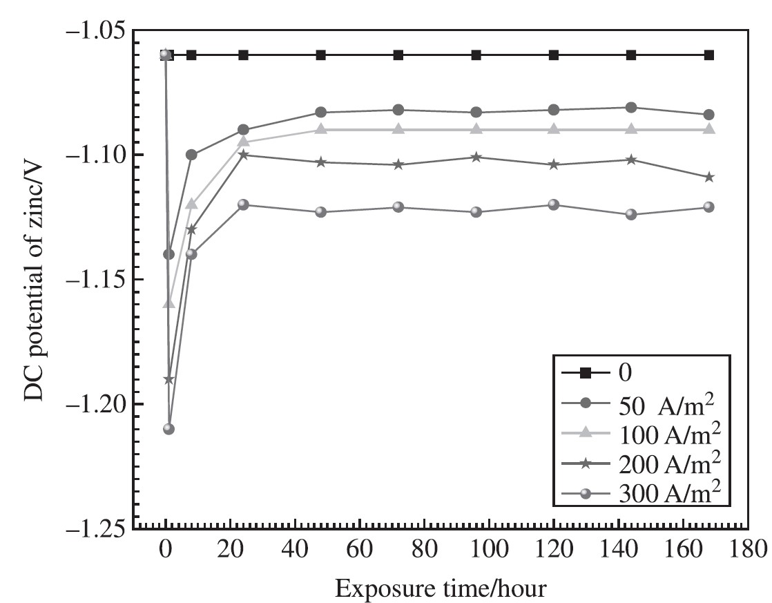
Figure 6: Records on DC potential of Zn anode under various AC [14].
In both cases, the corrosion rate was measured by weight loss experiments on Zn following exposure to different conditions for 7 days as depicted in Figure 7. The fact that AC greatly accelerated up Zn corrosion is self-evident. In the first scenario, in the absence of AC, the Zn corrosion rate was 0.14 mm/yr.
The corrosion rate climbed to 0.73 mm/yr, which is four times higher than the rate without AC, when the applied AC density reached 100 A/m2. When the ac density was 300 A/m2, it reached 0.83 mm/yr.
Furthermore, it is essential to point out that the rate of Zn corrosion in Scenario 2 was significantly higher than the rate of Zn corrosion in scenario-1 under varied AC conditions. The rate of corrosion in scenario-2 was 0.77 mm/yr when there no AC was applied, which was five times higher than the rate in Scenario 1.
Under the conditions of an AC density of 50 A/m2, the rate of corrosion in Scenario 2 climbed to 1.95 mm/yr, which was much higher than the rate in Scenario 1, which was 0.58 mm/yr. The corrosion rate in Scenario 2 was 4.05 mm/yr due to an AC density of 200 A/m2, but the corrosion rate in Scenario 1 was much lower, coming in at 0.80 mm/yr.
At the point where the applied AC density reached 300 A/m2, the rate of corrosion in Scenario 2 was six times higher than the rate in Scenario1.
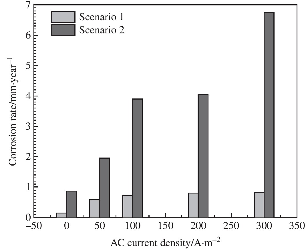
Figure 7: Corrosion rate determined by weight loss tests of Zn after being exposed to various AC for 7 days in both scenarios [14].
Within the context of scenario-1, additional research was conducted to investigate the rate of corrosion and the weight loss of the Zn ribbon anode. It was discovered in Figure-8 that the free-corrosion rate without AC was 0.15 mm/yr. As soon as AC was applied, the rate of corrosion increased. The corrosion rate was 0.44 mm/yr when the AC current density was 20 A/m2, but it reached 0.58 mm/yr when the current density was 50 A/m2 and 0.73 mm/yr when the current density was 100 A/m2.
The corrosion rate reached 0.8 mm/y for 200 A/m2 and 0.83 mm/yr for 300 A/m2, respectively. One possible equation that may be used to explain the link between the rate of corrosion and the AC current density is as follows [15]:
Where,
Vcorr: is the corrosion rate of Zn, mm/yr.
Iac: is the RMS value of AC current density, A/m2.
a = -0.65.
b = 43.48.
and c = 0.81.
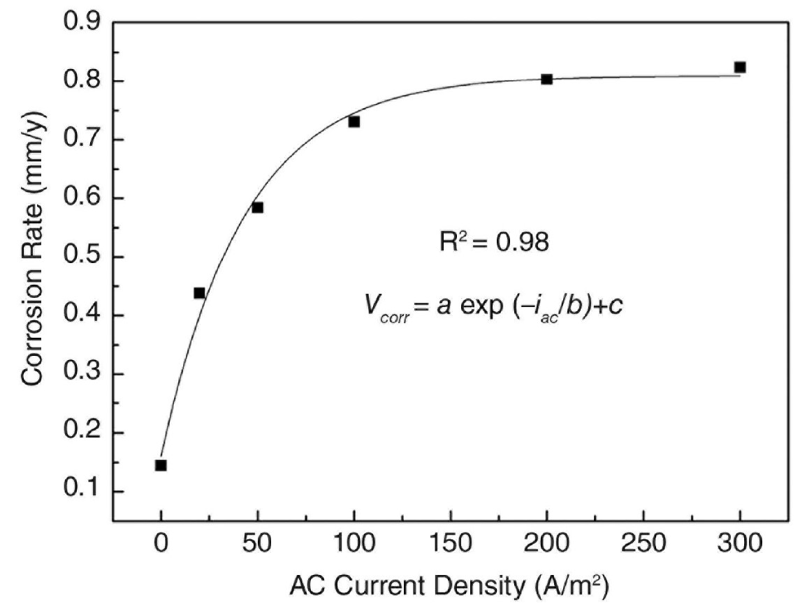
Figure 8. Corrosion rate obtained by weight loss tests of Zn subjected to various AC current densities [15].
The results of the weight loss tests demonstrated that the rate of corrosion of Zn under AC conditions of 100 A/m2 in scenario-1 was comparable to that of the Zn sacrificial anode, which had a current density of 0.46 A/m2 in the CP configuration.
During the course of the work, AC current efficiency (CE%) was researched in order to further investigate the reason and provide a realistic reference for the service life of the design of Zn ribbon. CE% was defined as the ratio of weight loss caused by AC to weight loss caused by an equivalent level of DC. Figure-9 illustrated the percentage of AC current efficiency that occurs during the Zn corrosion process.
Under the case that no AC was being applied, it was clear that the CE% was approximately 1.7%. In addition, the drop in CE% was a direct result of the rise in the density of AC current. Approximately 1.63% of the CE was present when the applied AC current density was 20 A/m2.
The percentage of CE decreased to 0.87% when the AC current density was 50 A/m2. The percentage of CE decreased even further, going from 0.54% to 0.21% for 100 A/m2, 200 A/m2, and 300 A/m2.
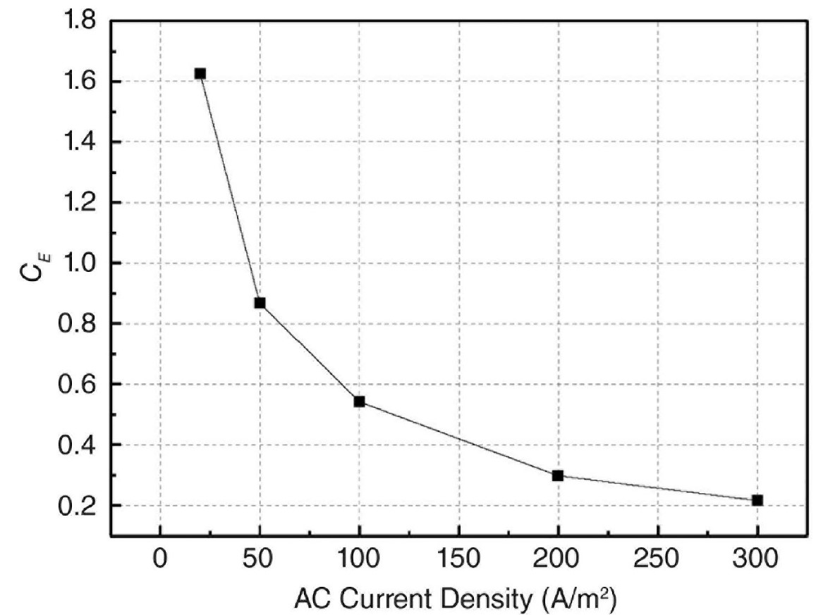
Figure 9: AC Current efficiency (CE%) of Zn at various AC current densities [15].
The author presents the results of a further investigation, which are presented in Table 2. This table illustrates the estimated rate of AC corrosion of Zn ribbon anode under a wide range of AC current density, the equivalent DC current density (defined as the DC current density will cause the same rate of corrosion caused by the corresponding AC current density), the percentage of the DC current density to the AC current density, and finally the estimated annual weight loss per unit surface area.
The corrosion rate is 0.175mm/yr when the AC current density is 1A/m2, but it reached 0.217mm/yr when the current density is 4A/m2 and 0.294mm/yr when the current density is 10A/m2. At an AC current density of 50A/m2, it increased to 0.60mm/yr which is approximately three times higher than the rate without AC.
The corrosion rate climbed to 0.74mm/yr, which is approximately four times higher than the rate without AC, when the applied AC current density reached 100A/m2. At AC density 200A/m2 and above; the variance of the estimated corrosion rate is minimized and could be considered that the maximum corrosion rate of Zn ribbon anode is approximately 0.81mm/yr regardless the value of AC current density.
The results of the estimated corrosion rate demonstrated that the rate of corrosion of Zn under AC conditions of 1A/m2 is comparable to that of the Zn sacrificial anode, which had a current density of 0.117 A/m2 in the CP configuration with a ration of DC to AC current density is 11.7%. In addition, the drop in ratio of DC to AC current density is a direct result of the rise in the density of AC current.
Approximately 6.34% of the ratio of DC to AC current density is present when the applied AC current density is 2A/m2. The ratio is decreased to 3.09% when the AC current density is 5A/m2. The ratio is decreased even further, going from 1.97% to 0.81% for 10A/m2 and 50A/m2.
The predicted annual weight loss per unit surface area is a significant aspect that should be taken into consideration. In situations where the current density is 1A/m2, the value is 1.25kg, whereas in situations where the current density is 15A/m2, the value is 2.5kg. When compared to the weight loss that would occur in the event of a current density of 1A/m2, this is nearly twice as much.
Compared to the weight loss that is linked with a current density of 1A/m2, the weight loss that occurs when the AC current density is 100A/m2 is nearly four times more. To be more specific, it climbed to 5.3kg at this current density.
Table 3: Estimated AC corrosion rate, DC to AC current density ratio and annual weight loss per unit surface area.
|
AC current density (A/m2) |
Corrosion rate in (mm/Yr) |
Equivalent DC current density (A/m2) |
Equivalent DC to AC current density ratio (%) |
Weight loss in (Kg/m2/Yr) |
|
0.1 |
0.160 |
0.108 |
108 |
1.156 |
|
1 |
0.175 |
0.117 |
11.71 |
1.251 |
|
2 |
0.189 |
0.127 |
6.34 |
1.354 |
|
3 |
0.203 |
0.136 |
4.54 |
1.455 |
|
4 |
0.217 |
0.146 |
3.64 |
1.554 |
|
5 |
0.231 |
0.155 |
3.09 |
1.651 |
|
6 |
0.244 |
0.163 |
2.72 |
1.745 |
|
7 |
0.257 |
0.172 |
2.46 |
1.837 |
|
8 |
0.269 |
0.180 |
2.26 |
1.927 |
|
9 |
0.282 |
0.189 |
2.10 |
2.015 |
|
10 |
0.294 |
0.197 |
1.97 |
2.101 |
|
15 |
0.350 |
0.234 |
1.56 |
2.503 |
|
20 |
0.400 |
0.268 |
1.34 |
2.860 |
|
50 |
0.604 |
0.405 |
0.81 |
4.324 |
|
100 |
0.745 |
0.499 |
0.50 |
5.331 |
|
200 |
0.803 |
0.539 |
0.27 |
5.751 |
|
250 |
0.808 |
0.541 |
0.22 |
5.783 |
|
AC current density (A/m2) |
Corrosion rate in (mm/Yr) |
Equivalent DC current density (A/m2) |
Equivalent DC to AC current density ratio (%) |
Weight loss in (Kg/m2/Yr) |
|
0.1 |
0.160 |
0.108 |
108 |
1.156 |
|
1 |
0.175 |
0.117 |
11.71 |
1.251 |
|
2 |
0.189 |
0.127 |
6.34 |
1.354 |
|
3 |
0.203 |
0.136 |
4.54 |
1.455 |
|
4 |
0.217 |
0.146 |
3.64 |
1.554 |
|
5 |
0.231 |
0.155 |
3.09 |
1.651 |
|
6 |
0.244 |
0.163 |
2.72 |
1.745 |
|
7 |
0.257 |
0.172 |
2.46 |
1.837 |
|
8 |
0.269 |
0.180 |
2.26 |
1.927 |
|
9 |
0.282 |
0.189 |
2.10 |
2.015 |
|
10 |
0.294 |
0.197 |
1.97 |
2.101 |
|
15 |
0.350 |
0.234 |
1.56 |
2.503 |
|
20 |
0.400 |
0.268 |
1.34 |
2.860 |
|
50 |
0.604 |
0.405 |
0.81 |
4.324 |
|
100 |
0.745 |
0.499 |
0.50 |
5.331 |
|
200 |
0.803 |
0.539 |
0.27 |
5.751 |
|
250 |
0.808 |
0.541 |
0.22 |
5.783 |
Conclusions
The effect of DEH on the Al anode performance should be given higher attention as a significant influence was illustrated for the corrosion behavior of sacrificial Al anodes under application of AC. Corrosion of the anodes, resulting from current provided for the protection of the steel and self-corrosion, occurred at an increasing rate with applied AC level.
The experimental study [3] has demonstrated that steel does not receive adequate protection from sacrificial anodes when AC is applied. This demonstrates that there is a drop in the efficiency of the anode when AC current is present.
Furthermore, the author [1] described the impacts of the DEH system on the performance of the Al anodes; this is evidence that the effects of the CP anodes on the DEH system and vice versa should be taken into consideration.
There is no doubt that the performance of the Mg anode is affected when AC power is present. If there was AC interference present, the DC potential of the Mg anode would move in a positive direction. In addition to this, the rate of corrosion of the Mg anode is increasing at a quicker and faster pace as the AC interference voltage increases.
The accumulation of corrosion products on the surface of the Mg anode has an effect on the amount of electric charge that is released. It was an indication that the cathode control was gradually transitioning into the anode control structure. It demonstrated that AC voltage played a significant part in the anodic polarization of the Mg anode [11&12].
The reported works [13,14&15] carried out to investigate the effect of AC on corrosion of Zn ribbon anode came to the conclusion that AC current significantly accelerated the corrosion of Zn in the scenarios with or without dc decoupler.
In both cases, the charge transfer resistance of Zn was significantly reduced as a result of alternating current, which would result in a significant rise in the rate of corrosion. This is despite the fact that the effects of AC on electrochemical corrosion of Zn ribbon anode are still not fully understood. It was demonstrated that the corrosion product film that was developed on the Zn surface first increased as a consequence of the effects of AC current, and then progressively disappeared as a result of AC oscillation.
An estimate was made for the ratio of the weight loss induced by AC current to that caused by a comparable steady-state direct current density. This ratio is referred to as the AC current efficiency. When the applied AC current density was 20 A/m2, the results showed that the efficiency of the AC current was no more than 1.6%, and it decreased as the AC current density increased beyond that point.
A common problem that arises when subterranean pipelines are erected in the same corridor or in close proximity to energized high voltage transmission line is the occurrence of induced AC voltage. Two distinct processes are responsible for the generation of AC power on a pipeline.
The electromagnetic field that is produced by high voltage transmission line is the source of inductive coupling, which is an indirect electrical connection that results in voltages being induced on the pipeline. Conductive coupling, on the other hand, is a direct resistive coupling that occurs between a power system and the pipeline. In most cases, this would include a link between a power line and the ground, which results in ground fault currents, or a lightning strike that travels through the earth to reach the pipeline.
In situations where the inductive (steady state) coupling is the only thing that needs to be considered, the safety of the workers should be the first priority. In order to accomplish this, the operator of the pipeline is required to supply a dedicated ground that has a low resistance to earth.
This ground is necessary in order to guarantee that the induced AC voltages are brought down to safe values. By installing a Zn ribbon anode in parallel and connecting it to the victim pipeline through DC decoupler that allows AC to pass through while providing DC isolation, this strategy has the potential to be a successful mitigation technique for a wide variety of interference situations.
To mitigate the steady-state induced voltage, standard industrial practice involves the installation of one or more zinc ribbon anodes (grounding system) in parallel throughout the full length of the affected pipeline. The efficacy of the grounding mitigation approach is assessed by its ability to diminish the induced voltage to acceptable criteria.
Nonetheless, only one Zn ribbon anode may yield an exceedingly low grounding resistance compared to the resistance necessary to achieve the mitigation criteria [7].
The optimal design approach for mitigating AC steady state induced voltage necessitates determining the ideal grounding resistance and accounting for the AC corrosion of the Zn ribbon anode [13,14&15] to accurately estimate the necessary length and weight of the Zn anode, rather than indiscriminately employing a ribbon anode along the entire pipeline length.
Reference
- Ahmed Mahgoub. “Direct electrical heating impaction for subsea pipeline integrity,” Materials Performance Magazine. Vol. 60, No. 4, (2021), pp. 28-31.
- J.F. Williams, Alternating Current and Aluminum. Materials Protection, 1967: p. 50-52.
- Kari Forthun. “Alternating current corrosion of aluminum sacrificial anodes,” NTNU, Master Degree, 2013.
- DNV-RP-B401. “Cathodic Protection design,” 2021.
- Andreas Thorsteinsen. “Alternating current corrosion of cathodically protected steel in marine environment,” NTNU, Master Degree, 2012.
- Hesjevik & Olsen. “Cathodic protection design of submarine pipelines with direct electric heating,” Corrosion 2013, NACE, Paper No. 2443.
- Ahmed Mahgoub. “Mitigation of AC Induced Voltages on Buried Pipelines Influenced by E.H.V Power Lines. A Journal of Institute of Corrosion,” Corrosion Management, Issue 165, January/February 2022.
- S.R. Pookote, D.T. Chin. “Effect of alternating current on the underground corrosion of steels,” Mater. Perform. 17 (1978) 9–15.
- L.I. Freiman, M. Yunovich. “Special behavior of steel cathode in soil and protection assessment of underground pipe with a buried coupon,” Prot.Met. 27 (1991) 437–447.
- W.H. Bruchner, Soil corrosion of steel by AC, Mater. Protec. 4 (1965).
- Q. Ding, I. Chu, T. Shen. “Study on the Electrochemical Performance of Sacrificial Anode Interfered by Alternating Current Voltage,” International Journal of Corrosion Volume 2018.
- D. Tang, Y. Du, X. Li, Y. Liang, and M. Lu, “Effect of alternating current on the performance of magnesium sacrificial anode,” Materials and Corrosion, vol. 93, pp. 133–145, 2016.
- Lindemuth, H. Hernandez. “AC Mitigation and Cathodic Protection for a Long Regulated Pipeline,” CORROSION 2010, paper no. 105 (Houston, TX: NACE, 2010).
- Y. Du, and D. Tang. “Investigation on corrosion of zinc ribbon under alternating current,” Corrosion Engineering Science and Technology, vol. 50, 2015.
- M. Lu, and Y. Du. “Electrochemical Studies on the Performance of Zinc Used for Alternating Current Mitigation,” Corrosion, Vol. 71, No. 6, 2015.
Author: Ahmed Mahgoub is cathodic protection subject matter expert for Saudi Arabian Oil Company (Saudi Aramco) in Dhahran, Saudi Arabia. He has more than 18 years of experience in the consulting, engineering, constructing and commissioning of different cathodic protection structures. He is a NACE/ AMPP CP Specialist, Icorr CP specialist, and NACE/AMPP senior corrosion technologist.

Comments