
April 2010 Vol. 237 No. 4
Features
Multipath Ultrasonic Meters For Natural Gas Custody Transfer
Over the past 15 years, natural gas ultrasonic meters have transitioned from the engineering lab to wide commercial use as the primary device of choice to measure gas volume for fiscal accounting. Wide acceptance and use by gas pipeline companies has occurred during this time due to the device’s
- Reliability,
- Accuracy,
- Repeatability,
- Capacity (rangeability),
- Commercial availability that translates into product support, and
- Adoption of industry standards for fiscal measurement applications.
Briefly, the historical development of fluid velocity measurement in closed conduits with sonic pulses was first considered in the 1920s with discovery that transmission and reception of repetitive sound bursts could be used to describe the location and speed of moving objects; this principle was soon used to build sonar and radar arrays. Attempts were made over the years to apply the principle to measurement of fluid velocity in conduits, but it wasn’t until the development of economical high-speed electronics and digital signal processing in the late 1970s that a repeatable instrument with sufficient resolution for gas applications was devised.
Over the following decade and a half, the practical challenges of making the technology commercially viable as a flow measurement device were described and addressed through innovation and development that resulted in production of a gas ultrasonic meter that utilizes:
- Robust transducers that generate repeatable pulses (amplitude and frequency),
- Multiple paths to average axial velocity components over the cross-section of a closed conduit, (i.e. pipe),
- High-speed electronics complete with an accurate clock, to detect, resolve and time transmission and reception of sonic pulses with sufficient time-domain resolution.
- Combining transducer and electronics to permit high pulse transmission rates, and their transit time measurement, to allow rapid integration of fluid flow velocity so that accurate measured values can be reported once per second.
Virtually all ultrasonic meters used by pipeline companies for fiscal measurement are flow-calibrated at meteorologically traceable test labs. Flow tests are conducted at multiple points over the meter’s operating range to characterize its proof curve. Meter factor(s) are then calculated and applied to correct the meter’s output to the lab’s reference standards.
An advantage of modern ultrasonic meters is that once flow-calibrated, diagnostic assessments can describe whether proof, i.e. meter factor, shifts due to fault in the meter’s operating elements (i.e. transducers and/or processing electronics), so that re-calibration generally isn’t required (although some regulatory authorities mandate re-certification at set intervals: these mandates vary by jurisdiction).
Operating Principle
Knowledge regarding the measuring principle of ultrasonic meters lays a foundation for optimal field application as well as providing the basis for understanding whether the meter continues to accurately and reliably measure gas volume. Multipath ultrasonic meters that are typically used for gas custody transfer calculate gas flow rate from velocity measurements made over a pipe’s cross-section, using the following process:
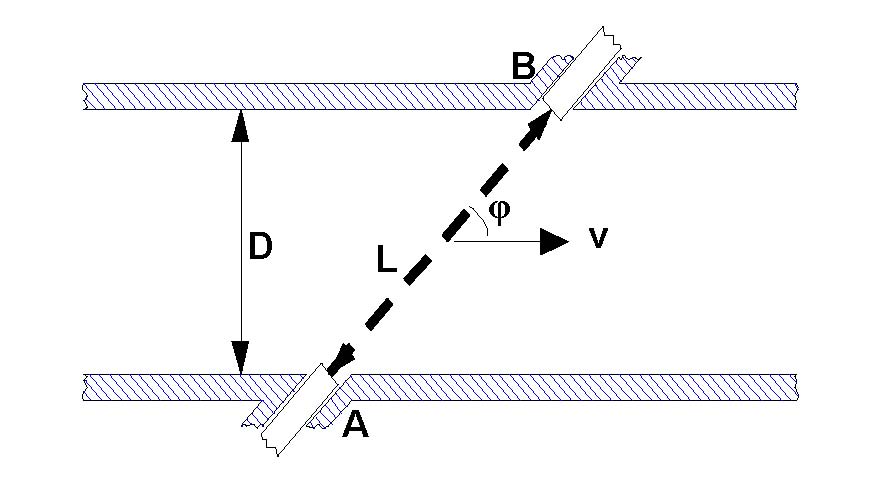
- Transducer pairs are installed in a meter body and are used to make transit time measurements of ultrasonic pulses which each transducer both transmits and receives. Pulses shot in the downstream direction are accelerated while those shot upstream are decelerated by the gas flow. (At 0 flow, transit times in the upstream and downstream directions are equal.)
- Velocities are calculated for each transducer pair, or path, from the measured transit time difference between pulses shot in the upstream and downstream directions.
- The multiple path velocities are averaged into the bulk velocity using a weighting scheme that depends on the path’s location in the pipe cross-section for which velocity is “sampled”.
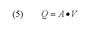
- Bulk velocity is multiplied by the meter body’s cross-sectional area to calculate uncorrected flow rate.
Velocity measurements are made along multiple paths using transducer pairs arrayed in known position in the meter body. Since the “absolute digital travel time measurement method” is employed (firing pulses in rapid succession in opposite directions across the same flight path in the pipe), fluctuations in pressure, temperature and gas composition don’t affect velocity measurement due to the nearly instantaneous sonic pulse emissions by individual transducer pairs.
Below are the basic equations(1) used for transit time measurement (eq. 1,2 ), bulk velocity (eq. 3), speed of sound (eq. 4), flow calculation (eq. 5) and a schematic (Figure 1) of a transducer pair’s geometry that puts the vector sums into context. Note that the only thermodynamic term in any of these equations is c, speed of sound. This is a fluid property, and the only term in these equations that varies with gas composition, pressure and temperature (i.e., fluid density).
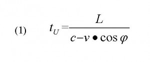
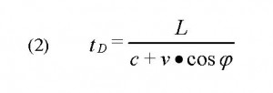


Solving for velocity, v, in equations 1 and 2, and combining their terms, results in the solution of interest: fluid velocity v (eq. 3). Note that the density dependent term, c (speed of sound) cancels and drops out of eq. 3. This is possible because that fluid density (i.e., composition, P and T) is assumed to be constant at the time when the upstream and downstream pulses are fired (a reliable assumption given that upstream and downstream pulses are fired within milliseconds of one another). The mutual effect, and therefore cancellation of c on the up/dn pulses, gives rise to the description of the meter’s operating principle as the “absolute digital transit time measurement method”. Application of the absolute digital transit time method provides the technique needed to render accurate gas measurement, and its integrity is dependent on:
- Knowledge of path length (distance traversed by ultrasonic pulses),
- Confirmation of clock accuracy (accurate transit time measurement),
- Validation of pipe cross-sectional area (accuracy in flow calculation, and transit time measurement),
- Validation of flow profile (accuracy of calculation of bulk velocity from individual path velocity measurements).
Diagnostic outputs monitored must verify the constancy of the key items in these bullets, in whole or part, to provide an assessment of the meter’s operating condition.
Application Considerations
All gas measurement technologies have limitations, including ultrasonic meters, and it is important for engineers and technicians who use any flow measurement technology to consider the limitations of the primary device proposed for use at a particular meter station prior to installation. Careful consideration before construction and installation can avoid costly re-work should the chosen technology prove less than optimal for the particular measuring station’s operating scenario.
Noise
As noted in the operating principle discussion, ultrasonic flow measurement depends on accurate transit time measurement of sonic pulses. Sound is characterized by its tone (frequency) and loudness (amplitude). In the case of an ultrasonic meter, the tone, or frequency of the pulses is above the range of human hearing (20 kHz), hence the modifier “ultra”.
Noise inside the pipe work can interfere with detection of sonic pulses if the noise is of coincident frequency with the meter’s transducers and drown out the pulse if it is sufficiently high in amplitude. If pulses are drowned out, detection, and therefore pulse transit time measurement, becomes impossible and flow measurement stops.
Designers should always be concerned regarding the possibility of noise interfering with an ultrasonic meter’s function, and should avoid installation near a noise source. That’s easy (and obvious) to state, but in practice, hard to accomplish since the most common noise sources are flow and pressure control valves which are nearly always co-located with meters at gas transfer stations. It is also notable that the noise offensive to an ultrasonic meter is inaudible to human hearing, so the valve sets that commonly cause interference are quiet or “whisper” trim-style valves.
These valves achieve their inaudible noise characteristic with trim designs that push the noise out of the range of human hearing, but into the ultrasonic range where UMs operate. Therefore, designers should install ultrasonic meters where they will be least affected by the noise generated by such valves. Most UM manufacturers can provide additional guidance particular to their product. In general:
- Meter installation: Install ultrasonic metering upstream of regulating devices.
- Noise reducers: Locate noise-attenuating elements between the meter and the noise source (tees, separators, etc.)
- Consult the meter manufacturer. They may have transducers of alternate frequency that are less susceptible to noise interference and/or the knowledge-base with respect to their meter’s response so that a proposed installation can be analyzed for possible impact based on valve type, flow and pressure drop, and then make recommendation for attenuators that mitigate against possible interference.
Dirt And Liquids
Dirt and liquids can impact the performance and accuracy of ultrasonic meters as it does all other flow measurement technologies. The effects vary, depending on the nature of the technology. For example, dirt gathering on the interior of an orifice tube or plate will have an impact on the dimensional characteristics upon which orifice meters rely. In the case of turbine meters, this may cause the meter to run slow due to increased bearing friction. In ultrasonic meters, concern exits with respect to transducer blockage and with dimensional integrity (diametral and path length changes).
With respect to diametral changes, recall that in an ultrasonic meter, velocity is measured and that uncorrected flow is calculated from the product of cross-sectional area and that measured velocity. A per cent change in area equates to a per cent changed in calculated flow. Therefore, there is a 1:1 relationship between diameter error and measurement error. Path length changes due to trash build-up on transducer faces also causes measurement errors, but these dirt-induced errors caused by path length change are easily detected using speed of sound comparisons (see Diagnostics).
Detection of dirt buildup in the meter causes larger measurement errors, but is harder to detect than for a dirt-induced path length change. Subtle diagnostic indicators can be monitored, but regardless the suspicion these indicators might flag, it is usually necessary to make a visual inspection and then clean the meter internals to eliminate the diametral reduction. Operators should:
- Make meter installations with a site assessment of the possibility for liquids/dirt contamination in mind and consider addition of inlet separators, filters and drains on the meter run to either prevent contamination from occurring or to provide a mechanism to drain liquids from the meter run.
- Consider installing the meter run with a mild slope to discourage accumulation of liquids down the length of the meter run and through the measuring section. Liquids will tend to accumulate at the lower end of the meter run which would also be the ideal location for a drain.
- Install inspection ports or even tees with uni-bolt closures to allow for visual inspection with a bore-scope and, in the case of inspection tees/caps, to permit for meter run cleaning.
- Adopt a regular program of diagnostic and visual inspection to detect buildup and avoid measurement errors due to diametral reduction.
Profile Distortion
As noted in the operating principle discussion, resolution of path velocities into a representative bulk, or average, fluid velocity, is essential to accurate calculation of uncorrected flow at line conditions. It is necessary to ensure the flow profile is consistent with that found during flow calibration and additionally that the profile is symmetrical (Figure 2) in shape so that the individual path weighting factors applied by the meter manufacturer retain their validity.

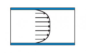
Figure 2: Laminar and Turbulent Flow Profiles.
Path velocities should be mapped during flow calibration and subsequent field inspections should compare the as-found flow profile to that documented when the meter factor was established during calibration in the flow lab.
Meter manufacturers usually employ different path configurations from one another in the quest to characterize the flow profile and accurately calculate bulk velocity: some designs are more effective in this regard than others, although arguments can be made that high performance flow conditioners, designed to generate consistent flow profiles, render this distinction moot. Regardless, whether a flow conditioner is used, it is still critical that a multipath meter provide indication when the as-found profile deviates from that expected (i.e. that from flow calibration). A good meter’s path design will enable calculation and reportage of swirl and asymmetry.
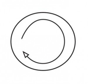
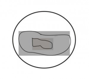
Figure 3: End view representations of Swirl and Asymmetry.
Profile distortions can occur due to meter-run obstructions, debris accumulation or surface roughness changes on the pipe wall and protrusions installed upstream of the meter (i.e., sampling probes or thermo-wells). However, the most common source of profile disturbance is standard pipe work such as tees, elbows and headers. These elements generate swirl, asymmetry or a combination of the two (Figure 3). General practices to ensure consistent flow profile include:
- Design meter runs that minimize profile distortions (long runs of straight pipe u/s of the meter), or include elements, such as flow conditioners, that normalize them. (Note: if users elect to use flow conditioners, the meter must be calibrated with the flow conditioner installed in the same position in the meter run, relative to the meter, at both the flow lab and field installations.)
- Select a meter design that employs a multipath design that properly characterizes the flow profile and can report via its diagnostics whether swirl and/or asymmetry are present.
- On initial meter start-up, map the flow profile again to check that the translation of the flow-calibrated meter system (meter run, meter and flow conditioner if used) to the field is valid: if the profile in the field is different than that measured at the lab, there is a shift in meter factor!
An area of continuing manufacturer research is to develop path designs that permit repeatable disturbance descriptions and measure their coincident impact on meter factor shifts. With this design and information on meter factor shift, it will be possible to correct meter output for the disturbance. This is a steep challenge since the degree and type of disturbances varies, and characterizing meter response to these many influences demands a large and statistically reliable body of accurate data.
All commercially viable gas ultrasonic meters offer diagnostic outputs that indicate meter-operating condition, up to and including the ability to judge whether volumetric output is accurate. The nature of the meter’s operating principle helps define these outputs and also their interpretation.
As noted, ultrasonic meters depend on transmission and recognition of sonic pulses using precise timing measurements and known geometry (path length and angle) to accurately measure gas velocity. Manufacturers have incorporated signal (pulse) recognition and processing algorithms as well as highly accurate clocks to make timing measurements. Therefore signal strength, signal to noise ratio, and clock accuracy are fundamental to accurate and reliable meter performance.
Conclusion
Ultrasonic meters are the overwhelming technology of choice for large-capacity gas measurement stations because of their reliability and rangeability. Speed of sound diagnostics inherent in these transit time meters, coupled with industry-established speed of sound calculations based on gas properties, yield the additional advantage of providing a simple technique to validate meter integrity in the field.
Manufacturers evaluate design options and adopt technologies best-suited to their intellectual property and cost-benefit analysis. The goal is to provide customers a reliable and economical solution to their flow measurement challenges, but because of necessary trade-offs, performance of individual meters varies and users should evaluate them on the basis of the technology that best suits their individual firm’s operational needs.
Bibliography
1. AGA TMC Report No. 9, “Measurement of Gas by Multipath Ultrasonic Meters”, copyright 2007, American Gas Association.
2. RMG, “USZ-08 Operating Manual”, Copyright 2006, RMG GmbH

Comments