
December 2012, Vol. 239 No. 12
Features
The Nature Of Polyethylene Pipe Failure
Polyethylene (PE) pipes and fittings are used extensively in distributing natural gas and water safely, reliably and economically, and enjoy an excellent performance track record. PE offers the pipe industry:
• Economical, high volume manufacture – extrusion, injection moulding;
• Design flexibility – easily shaped;
• Integrated design – multifunction, ready assembled components – couplers and fittings;
• Low material cost;
• Light-weight design – ease of transport and handling;
• Flexibility – ease of transport and handling, use in conjunction with trenchless technologies and resistance to seismic activity;
• Relative ease of jointing (compared to metallic pipe systems);
• Corrosion and chemical resistance;
• Biologically inert capabilities;
• Toughness, impact resistance, abrasion resistance and long term durability – technical lifetime of >50 years;
• Low temperature performance;
• Leak-free fusion jointing – low maintenance costs;
• Low friction bore – no scale build-up and efficient flow of transfer medium; and
• Environmental benefits – recyclable.
Today, PE is highly engineered and provides a good balance of strength, stiffness, toughness and durability meeting the demands of the gas pipe industry.
The failure of PE pipe systems is typically due to older generation materials whose properties offer limited resistance against severe environmental and operating conditions. The other factor is human error, committed in the supply chain and site construction of installed pipe systems.
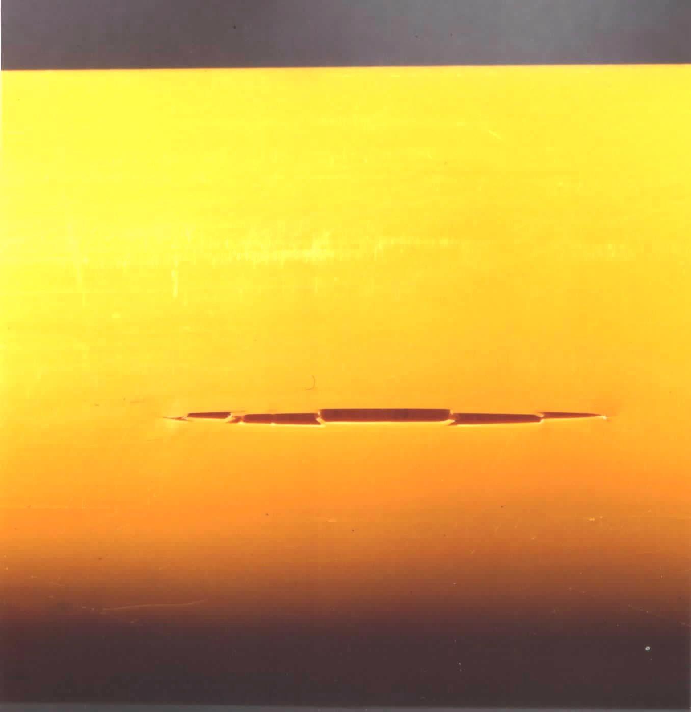
The general mode of field failure reported for PE pipe is brittle, slow crack growth (SCG) through the pipe wall. These cracks can initiate at microscopic stress-raising flaws. These brittle mechanical failures are typically slit-type fractures that lie parallel to the pipe’s extrusion direction. Circumferential hoop stress in the pipe wall is the driving force for crack opening. Typical slit type fractures are shown in Figure 1.
Circumferential cracks can also be initiated on either the outside or inside surface of pipes due to secondary stresses such as bending or impingement on the material. The premature failure of melt-fused joints is also common failure where cracking initiates at stress concentrations created by poor installation practices.
Visually, brittle cracks are typically smooth, featureless and devoid of any yielding and deformation process, as shown in Figure 2.
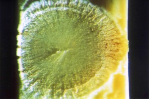
Figure 2: Brittle fracture surface.
There are three major failure modes for PE pipe, as shown in Figure 3.
Figure 3: Failure modes of PE pipe – internal hydrostatic pressure testing
Ductile failure Mode I results in yielding and reflects a material’s propensity to undergo large-scale, irreversible “plastic” deformation when under stress. The mechanism results in localized expansion of the wall section and final rupture of the deformed zone as shown in Figure 4.
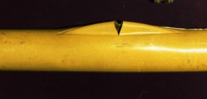
Figure 4: Ductile failure of PE pipe under internal hydrostatic pressure
Failure Mode II is associated with Creep, Creep Rupture and SCG.
Creep is time-dependant, non-reversible deformation, when exposed to a constant tensile stress. Creep rupture is the terminal event of creep and is a measure of the time that a material under a constant, applied tensile load takes to fail. Creep rupture can be accelerated by:
• Temperature
• Stress concentrations
• Fatigue
• Chemical environment.
Figure 5 is representative of a creep rupture curve where the ductile-brittle transition signals the onset SCG.

Figure 5: Creep rupture curve
The events that lead to Creep Rupture are shown in Figure 6. After crack initiation, voids develop ahead of the crack. These voids gradually merge into larger voids that are spanned by highly orientated load-bearing fibrils. This process, known as Crazing, continues until a point is reached when the most highly stretched fibrils will rupture resulting in fracture.
Figure 6: Sequence leading to SCG.
For PE, the tenacity of fibrils and their resistance to rupture will be highly dependent on molecular architecture, particularly molecular weight, molecular weight distribution, branching, crystallinity and tie molecules. The tie molecules are embedded in the crystallites and transverse amorphous regions, acting as mechanical links between the crystalline domains, and play a decisive role in the resistance to fibril failure and overall mechanical properties when subjected to stress.
Mode III failure is related to degradation and embrittlement of the plastic due to thermo-oxidation with time.
In the late 1970s, workers at British Gas R&D (subsequently Advantica and, now, GL Noble Denton) discovered that thick wall MDPE pipes operated at a critical pressure and below a critical temperature could fail catastrophically by sustained, axial rapid crack propagation (RCP), as shown in Figure 7 and Figure 8.

Figure 7: Rapid crack propagation (RCP).
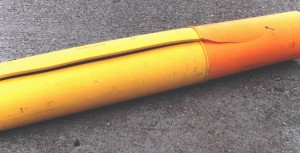
Figure 8: RCP arrest in PE100 pipe.
RCP can be initiated due to either a defective butt joint, third-party damage, such as a high-velocity impact from excavation equipment, or a pipeline pressure pulse. Once initiated, ruptures can travel at high speed along the length of the pipe over significant distances as long as the stored energy from the contained pressure source is sufficient to drive the crack faster than the rate at which the energy is released.
At a critical speed approaching the speed of sound, the crack will become unstable, branching in a sinusoidal pattern, until it slows and stops. RCP is dependent on several factors:
• Pipe diameter – as outside diameter increases, the possibility of RCP increases;
• Operating pressure – as pipeline stress/pressure increases, the possibility of RCP increases;
• Operating temperature – as temperature decreases, the possibility of RCP increases; and
• The pipe material’s resistance to impact fracture and resistance to RCP.
RCP failure of PE pipe is rare but the potential dire consequences are significant for gas distribution (Figure 9). RCP resistance is now designed into pipes so it may be avoided under worst case scenarios. In order to complement this requirement GL Noble Denton has built a full-scale (FS) RCP test facility at its Spadeadam Test Site in the UK, which meets the requirements of ISO 13478.
The FS test is considered to be the most reliable method for assessing RCP resistance. It is designed to reproduce idealized service conditions for a pipe in service. Extensive RCP testing conducted by the company identified safe operating pressures such that RCP has never been recorded within the UK Transco PE distribution network.
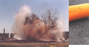
Figure 9: Full-scale rapid crack propagation (RCP) test at Spadeadam, GL Noble Denton’s test center.
GL Noble Denton also works in the modeling of gas mains failure and consequences, in particular estimating the risk associated with metallic mains failure in order to prioritize replacement. In support of this activity GL Noble uses a powerful decision support tool called Mains Replacement Prioritization.
The same methodology can be applied to PE mains, especially those laid with earlier, more vulnerable jointing techniques, so that the combination of failure model and location near to property can be taken into account.
Summary
PE pipeline networks have established an impressive safety record over the years, and are the preferred material of choice in the construction of gas and water distribution networks.
However, failures can occur for an assortment of reasons including: system design, manufacturing practices, installation practices, accidental damage, incorrect material selection, thermal exposure, stressing beyond anticipated design stress, point loading and stress raisers, weathering, chemical exposure, and soil conditions.
Author
Dr. Chris O’Connor is Senior Consultant (non-metallics) at GL Noble Denton, providing polymer consultancy support to a global network of oil and gas clients. He has extensive polymer knowledge, specializing in material selection, specifications and standards, product qualification and failure analysis.

Comments