May 2019, Vol. 246, No. 5
Features
TANAP’s Seismic Fault Crossing Posed Challenges For Welding
By Arash Shadmani, and Ismael Ripoll, Welding Specialists, TANAP
The Trans Anatolia Natural Gas Pipeline (TANAP) transports Azeri gas from the Shah Deniz field through Turkey and Europe via the South Caucasus Pipeline (SCPX) at the Georgia/Turkey border, and the Trans-Adriatic Pipeline (TAP) at the Greece/Turkey border.
Complicating matters within Turkey is the North Anatolian Fault (NAF), which is an active right-lateral, strike-slip fault of the northern Anatolia region. It runs along the transform boundary between the Eurasian Plate and the Anatolian Plate.
A seismic fault can be classified as a planar fracture or discontinuity in a volume of rock where the fault ruptures and the accumulated strain energy is released in part as seismic waves, normally resulting in earthquakes.
The conventional stress-based welding codes, such as API 1104,1&2 ISO 138473 or BS 4515-14, do not address adequately the strain-based design approach for welding and associated acceptance criteria5.
Experimental Procedure
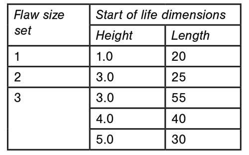
NAF seismic fault has the highest designed peak tensile strain of up to 3.66%. Fracture mechanics approach used to establish the acceptance criteria for mainline m-GMAW (mechanized gas metal arc welding) procedure of the TANAP pipeline to be used for the seismic fault crossings. The most severe scenario is assessed by considering open-to-surface planar sharp flaws at two possible locations in the girth weld, with the plane of defect perpendicular to the tensile stress (Figure 1). Initially, three sets of acceptable flaw sizes were evaluated and required minimum fracture toughness to be achieved are defined.
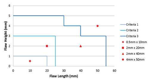
Figure 2 shows a plot of the flaw size represented by these flaw sets. In addition to this, four example flaw sizes are included to indicate whether a flaw size is acceptable or not. For instance, 0.5-mm by 10-mm, 2-mm by 20-mm, and 2-mm by 40-mm flaws fall within flaw set 1, 2 and 3, respectively. However, the 4-mm by 50-mm flaw falls outside of all three acceptance flaw sets and is, therefore, unacceptable.
Screening Assessment
Screening assessment by considering the onset of tearing at the weld flaw (tearing of the weld flaw is not permitted) is carried out. In this approach, the value of the crack driving force parameter “J-Integral” is extracted from the finite element (FE) and run with the flaw considered. For the longitudinal strain and the minimum required value of the crack tip opening displacement (CTOD) is extracted in accordance with DNV-OS-F1016.
*API 5L X70 modified grade with minimum yield strength of 530MPa8
Where:
υ: Poisson’s ratio
J: is the value of the J-integral from the FE run
YS: is the yield strength used in the FE analyses
X: is the conversion factor. Appendix A, A403 of DNV-OS-F101 refers to BS79107 to calculate the conversion factor. However, a conversion factor equal to 1.5 has conservatively been used.
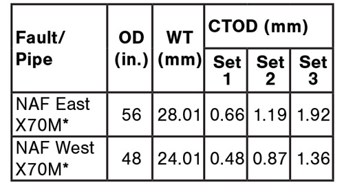
Table 2 summarizes the minimum crack tip opening displacement (CTOD) required for each of the flaw size set for NAF fault crossing.
The minimum CTOD obtained value during welding procedure qualification tests (WPQT) of mainline welding procedure, however, was 0.25 mm. This means none of the engineering defined acceptance flaw sets could be used.
Alternative Acceptance Criteria
for Embedded Flaws Only
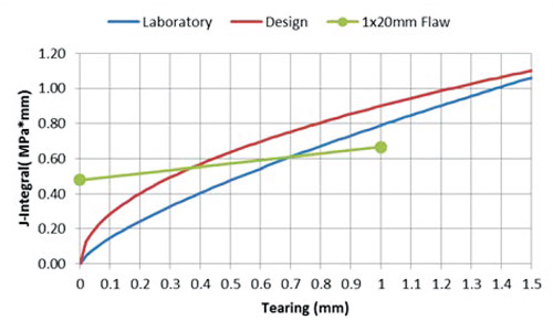
Engineering re-ran the assessment using the minimum CTOD obtained value of 0.25 mm in WPQT. Figure 3 shows the additional flaw size envelope for NAF East. This means no open-to-surface flaws are acceptable and only embedded flaws (Figure 3) can be tolerated.
Stable tearing assessment
To evaluate realistic conditions, the stable tearing assessment approach is adopted. Stable tearing assessment allows the onset of tearing at the flaw. In order to perform this type of assessment, the following additional data and results are required:
- J-R curve, which is a measure of the evolution of the fracture toughness with tearing of the flaw.
- Crack driving force parameter J-integral from the FE, for the initial flaw size and for the same flaw size increased due to tearing.
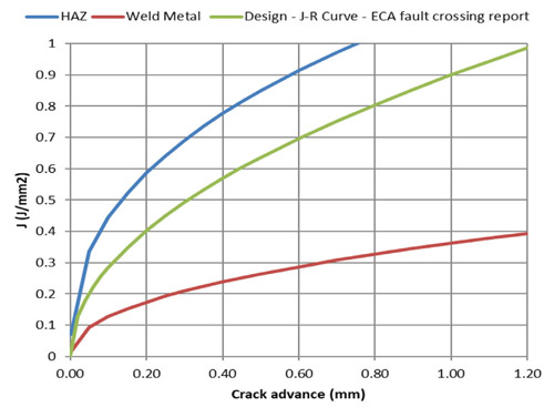
Figure 3 shows the J-R curves obtained during WPQT against what is required by engineering design to be able to use Set 1 of predefined acceptance criteria (Table 1). Weld metal curve that is way below the design requirement that J-integral for a practical flaw can possibly be applied through tearing assessment, which means the predefined acceptance criteria cannot be used.
Modifications
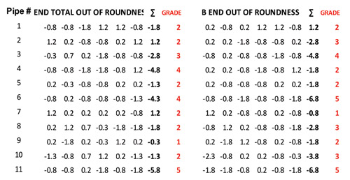
Base Material: All the pipes are handpicked for lowest yield-to-tensile ratio (Y/T) and Pcm (Ito-Bessyo carbon equivalent). Furthermore, a pipe ends dimensional survey is carried out to minimize the misalignment between adjoining pipes. Welding qualification are carried out on the pipes at the same heat as the production pipes.
Welding: To improve weld metal fracture touchiness behaviour, the filler is upgraded from ER70S-G to ER80S-G with additional nickel content. Also, interpass and preheat temperature are controlled, and no interruption is permitted during the welding. Welding is completed in one heat cycle and cooled down using thermal wrap in a controlled manner.
Fracture mechanics testing: In order to avoid over conservatism, a less constraining test using single-edge notch tension (SENT) specimens rather than conventional single-edge notched bend (SENB) specimens9 was used. To apply a more realistic approach and for comparison purposes, tests are carried out at both minimum operating temperature -7.5° C and minimum design temperature of -10° C.
Weld metal J-R curve at -7.5° C shows more resistance than the one at -10° C (Figure 5). This behavior is also in line with experimental comparison between SENB and SENT ductile brittle transition temperature (DBTT) curves10.
Results
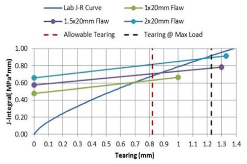
Figure 4 shows the improved J-R curve for weld metal that is much closer to design and can be used for tearing assessment of practical sets of flaws presented (Figure 5). The crack driving force rate from the FE model intersects the laboratory J-R curve at a tearing less than the tearing measured at the maximum load among the six weld center line (WCL) specimens that were broken to produce the J-R curve. Therefore, the weld produces enough toughness to stop the continuation of tearing.
The FE model was further re-applied with larger flaws than 2-by-20 mm, but acceptable conditions were not achieved for these flaws, and the results from these runs were disregarded.
Construction Methodology
In order to apply the produced acceptance criteria into construction a specific construction, methodology had to be implemented:
- Pipes heat selection (best heat in terms of Y/T and Pcm)
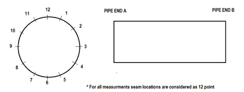
- Pipe ends dimensional survey (Figure 6)
- Pipes stringing plan, ordering adjoining pipes with minimum misalignment
- Bevel preparation subject to near ±0 tolerances
- Fit-up to the minimum allowable misalignment (Figure 7)
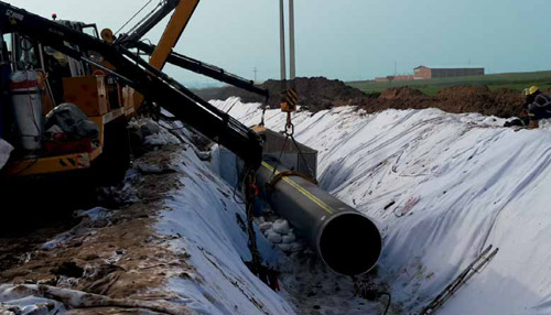
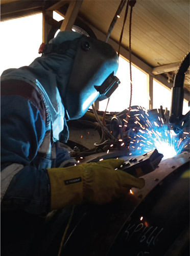
- In trench welding (Figure 8)
- Minimum possible heat-input
- Strict preheat and interpass control (No interruption is allowed)
- One station welding (completing the welds without interruption) followed by in line NDE (non-destructive evaluation)
- Alternatively lowering without bending by calculated allowable span length between side booms and secondary NDE after installation for final acceptance.
- Zero tolerance – no repair allowed
Conclusion
With applied welding procedure modifications and more realistic fracture mechanics testing, fracture resistant behavior of the weld metal improved significantly. Therefore, a practical flaws set with a height up to 2 mm and lengths of 20 mm can be tolerated.
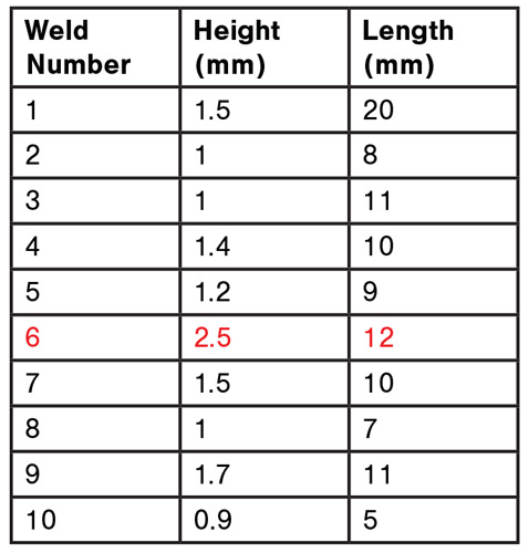
By applying this rationalized acceptance criteria and following the specific construction/installation methodology, the construction of NAF seismic fault crossings became practical, and the production rate increased from zero to 90% (one cut-out in 10 welds) without compromising quality nor integrity. P&GJ
References:
Implementation of engineering critical assessment and fitness for purpose approach on TANAP pipeline welding, Arash Shadmani, Pieter Erasmus, 19th International Metallurgy and Materials Congress, Istanbul, Turkey, 25/27 October 2018.
API 1104 Welding of pipelines and related facilities, 21st edition, 2013.
ISO 13847 Petroleum and natural gas industries Pipeline transportation systems - Welding of pipelines, 2nd edition 2013.
BS 4515-1 Specification for welding of steel pipelines on land and offshore, 2009.
Guidelines for the seismic design and assessment of natural gas and liquid hydrocarbon pipelines, Pipeline Research Council International Catalog No. L51927, 2004.
DNV-OS-F101, Submarine pipeline systems, 2013.
BS 7910, Guide to methods for assessment of flaws in metallic structures, 2013.
API 5L Specification for line pipe, 45th edition, July 2013.
Determination of quasi-static fracture toughness and fracture resistance curves for onshore and offshore pipeline systems, Uygar Tosun, Koray Yurtışık and Süha Tirke, 19th International Metallurgy and Materials Congress, Istanbul, Turkey, 25/27 October 2018.
SENT testing standard BS 8571 and its ongoing development, Philippa Moore, The Welding Institute, Webinar, 2017.





Comments