
February 2020, Vol. 247, No. 2
Features
Embedding Operating Procedures in Pipeline SCADA
By Keith Ferguson, Vice President, Pipeline Energy Dynamics Intl (PEDI)
The pipeline supervisory control and data acquisition (SCADA) operator has one of the most critical jobs in the pipeline industry and should be given all the help available to keep pipelines safe and liquid flowing. To this end, more than 25 years ago, a major oil company determined that SCADA-embedded operating procedures and safety features were needed to improve safety.
The selected method placed the operating procedures inside the SCADA system to increase pipeline safety and prevent incidents on the various pipelines. With management support, these safety and operating procedures were embedded in all SCADA systems, and since the features were so effective, they are required today in replacement SCADA systems.
After completion of the embedded operating features, the Department of Transportation (DOT) audited the operating procedures in the SCADA system and determined it was the safest they had ever checked. Currently, the Pipeline and Hazardous Materials Safety Administration (PHMSA) is emphasizing the requirements for leak detection on pipelines in hazardous areas, and the pipeline industry is implementing SCADA as an aid to minimize environmental damage and associated costs.
Joining the conversation are all the sellers of leak detection solutions, touting their solutions as the answer. While this is a useful requirement when a leak occurs, another area that should be a part of the discussion is embedding the pipeline operating procedures into the SCADA system to aid the operator in running the pipelines safely.
High line pressure and high manifold pressure shutdown tables were the first features installed. To ensure that safety features were active, each pipeline had a separate active personal computer (PC) with the high line and high manifold shutdown tables monitoring communications with the remote terminal units and the master SCADA computer. Later, systems moved the shutdown tables to the main computer. When a high line, high manifold or ruptured disc was detected, its shutdown table was activated to relieve the pressure on the pipeline without operator intervention.
Flow path verification tables were installed in the SCADA system to ensure a safe startup of the pipeline when starting a pump station. When the operator tried to issue a pump start command at a pump station, the SCADA software would find the pump in the flow path table to check downstream for block valves being open and for a delivery valve being open.
If a block valve was closed or a delivery valve was not open, the command to start the pump could not be sent unless it was overridden by the operator. These flow path verification tables ensured the operator did not start a pump against closed valves and overpressure the pipeline.
Valve close commands were verified before the operator could issue the command. If the close command was to a delivery valve, the SCADA would check upstream and downstream to see if a block valve was closed or a flow path was open to a delivery valve. If not, the SCADA system would check downstream to see if a block valve was closed or a delivery valve was open. If not, the command could not be issued unless overridden by the operator.
Connected to each delivery valve was the manifold and tank valve open/close table, which determined the procedure for the opening of the valves behind the delivery valve.
The tank valves were to be opened first and then the manifold valves proceeding to the delivery valve. The valve close procedure for these valves was the reverse of the open procedure. These procedures ensured that a flow path was open to the delivery tank.
Operating limits that bracketed the current meter rates and pressures for limit violation would notify the operator of a segment upset. These limits bracketed the current reading and were separate from the actual high and low limit values for the pipeline.
Segment Numbers
An assigned segment number was the identifier for determining the operating high and low limits for meter rates and low limits for pressure. The operating limits were always active and could only be turned off on a segment. If an upset occurred, it would automatically rebracket the current readings.
If the high limit/low limit occurred, the operator received a limit violation message. After a delay, the system automatically bracketed the current meter rates and current pressure to a set value for the different segments of the pipe. If the alarms such as a high manifold, highline pressure or rupture disc occurred, the operating limits for that section of the pipeline would be turned off to allow readings on the pipeline to stabilize.
The operating parameters would also be turned off when a pump station went down or commanded on or off. Once the pipeline was stable again, the operating limits would automatically rebracket the current rates and current pressure on the pipeline segment. In addition to the operating parameters was the gravitometer reading high and low limit values notification. When the high and low limits were set at a specified value, the operator would be notified with a message when the gravitometer reading exceeded either the high or low limit.
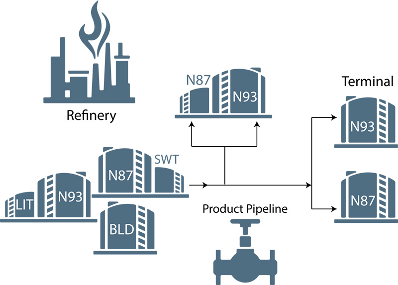
Checking the delivery meter grade against the tank grade was implemented to help the operator avoid contaminating the product in the tank. The grade in the meter would be checked against the grade in the tank. If the wrong grade was being delivered to the tank, a grade mismatch occurred, and the operator would be notified of the grade mismatch.
The dampen the pressure wave feature was the last of table-driven software added since this pressure wave weakens the pipe in different upstream locations. The procedure functioned rapidly to limit stress on the pipeline by dampening the upstream pressure surge.
To simplify and prioritize the alarm messaging of the system, event messaging and alarm files were set up for each pipeline. In addition, each pipeline was assigned a display unit where its alarms and messages were displayed. Each was assigned to be a “critical,” “noncritical” or “warning” message.
This arrangement allowed the operator to focus his attention on important alarms and messages and avoid the clutter of all data being displayed on one single display unit when multiple upsets occurred on multiple pipelines. By dividing the warnings and alarms for a pipeline on separate areas of the display, the operator could focus on important alarms.
These operating and safety routines used the same routines with different sets of tables for each pipeline system’s operating procedures. After all the features were installed, the incident rate was dramatically reduced across all pipeline systems, which saved huge amounts of dollars. Most importantly, the pipeline SCADA operators readily accepted the procedures and requested the procedures be included in any replacement SCADA systems.
Author: Keith Ferguson is vice president of PEDI and has 30 years of experience in the design and implementation of scheduling software and SCADA systems globally. Ferguson holds degrees in mathematics and physics from the University of North Texas.

Comments