June 2021, Vol. 248, No. 6
Features
Options for Internal Inspection of Difficult-to-Check Pipelines
By Michael Beller and Carlos Enrique Sabido Ponce, ROSEN Group
(Editor’s note: This is the first of a two-part article. Part 2 will appear in the July issue of P&GJ)
High-pressure transmission pipelines are and will remain part of the essential infrastructure for transporting large quantities of liquids and gases over long distances.
Primarily known for their use in the oil and gas industry, they will also play an important role in the up-and-coming hydrogen economy in the future, as well as in the water industry.
Pipelines are essentially cylindrical pressure vessels. Any medium transported must not leak out. Each built to a specific design pressure, they must be operated efficiently and effectively to ensure not just safety and environmental protection but also optimum performance.
Large varieties of parameters influence the operation of pipelines, such as pressure, flow, terrain, etc. In short, any influence on these parameters can change the functionality of the pipeline network as a transport system. The ultimate goal is to achieve the highest possible availability, along with the highest possible throughput.
This goal entails two major disciplines: mechanical integrity and process optimization. This article on the inspection of challenging pipelines addresses the former.
The article picks up where earlier publications left off, so let us briefly revisit these.1,2
For many years now, high-pressure pipelines have been inspected using inline inspection (ILI) tools. Starting with caliper tools and followed by metal-loss inspection tools, the industry today has access to a multitude of different solutions using a variety of nondestructive testing principles.
The majority of commercially available ILI tools can be sorted into three major categories: tools for detecting, sizing and locating defects in the pipe wall or the coating; tools for measuring centerline and pipe movement; and the recent class of new tools focused on material property classification and grading.3
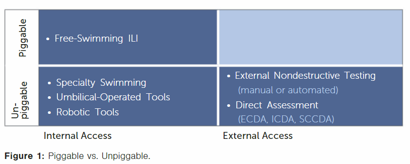
An important aspect is whether a pipeline can be inspected from the inside, or whether it needs to be inspected from the outside. (Figure 1)
Today, high-pressure pipelines are divided into three categories: traditional pipelines, difficult-to-inspect pipelines (sometimes referred to as challenging pipelines), and (truly) unpiggable pipelines.
Formerly, they were divided simply into “piggable” and “unpiggable” pipelines. The term piggable applies to pipelines that can be inspected using commercially available ILI tools, without the need to significantly modify or adapt either the inspection solution or the pipeline.
Until about a decade ago, pipelines that did not fall into the piggable category were considered unpiggable. Today, we have to differentiate these unpiggables into pipelines that still can be inspected from the inside, with all the associated benefits, and those pipelines that can only be inspected from the outside – the true unpiggables.
The major advantage of an internal inspection is that the entire section of pipe investigated is fully inspected, i.e., inspected with full axial and circumferential coverage. External inspection only allows limited access since it is not possible or feasible to dig up an entire pipeline section.
This paper focuses on the bottom left box of Figure 1. There are three different classes of specialized internal-inspection tools for difficult-to-inspect pipelines: a special class of free-swimming tools, umbilical-operated tools and robotic tools, i.e., tools that come with their own crawler unit and are truly autonomous.
Regardless of their differences, the mission of all ILI tools is always the same! These tools are used to collect data – data that are required as an input into effective integrity or defect assessments.
This mission requires two major capabilities: the right sensors to detect, size and locate relevant features, and the means to get the sensors to the “location of interest,” i.e., the spot or area where they need to measure. It is that second capability that differentiates traditional ILI tools, and those tools are designed specifically for the inspection of difficult-to-inspect pipelines.
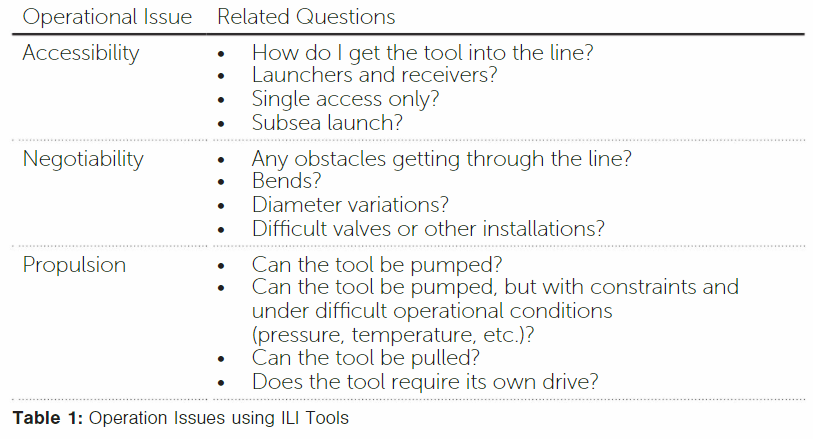
In short, ILI tools can be seen as complex mechatronic systems. The previous papers introduced the various non-destructive testing principles utilized in modern ILI tools. In this paper, we focus on the major operational issues regarding the inspection of challenging pipelines (Table 1).
Figure 1 introduced the three categories of ILI tools available for challenging pipelines. The major difference here is their mode of propulsion. Specialty free-swimming tools in design are close to traditional free-swimming tools. They are pumped through the pipeline being inspected.
The difference is that they are often modified for single access (bidirectional movement), or very confined spaces for launching or receiving (single-body tools also for small diameters), or tight bends. Umbilical tools make use of a tether or cable.
These different solutions are not in competition with each other but provide different elements of a toolbox to successfully inspect challenging pipelines. Each category of tools comes with its own specific strengths and weaknesses.
This means that one of the tool types may provide the capabilities most suitable for solving a specific inspection requirement. On the other hand, experience has also shown that the different tool types complement each other, resulting in optimal solutions when using them in combination.
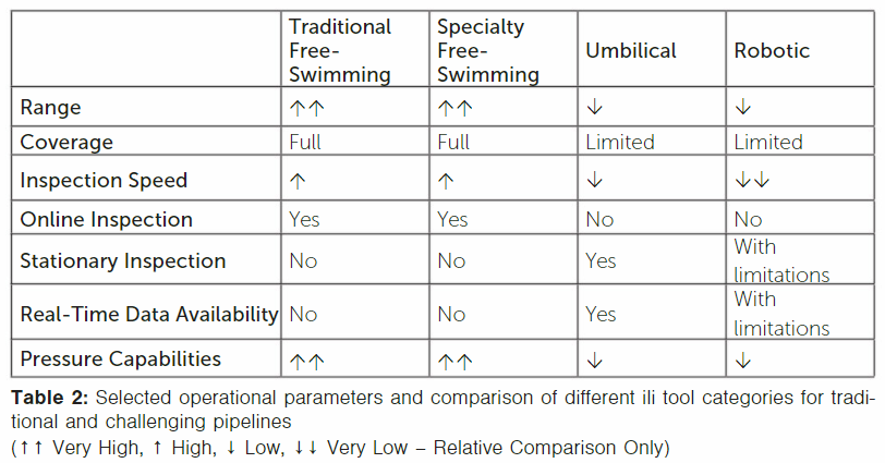
The operational parameters are explained as follows:
Range
Range defines how long a tool can actively travel in a single run. This is a function of energy supply and recording capacity, although the latter is not really a limiting factor anymore. However, the tools need an energy supply. Traditional tools, especially larger diameters, can carry a lot of batteries and, therefore, can inspect long distances at a time.
Inspection ranges of more than 620 miles (1,000 km) in a single run are possible. That said, the specialized free-swimming tools for challenging pipelines usually must be shorter and may only consist of a single body.
There are cables available with a length of up to approximately 9.3 miles (15 km). If a pipeline is accessible from both ends, this would result in a potential inspection range of 18.6 miles (30 km).
However, that number normally cannot be achieved. The reason: bends. Pipelines are not always straight; they have bends. In a bend, the cable will touch the wall and cause friction. These frictional forces limit the effective length for which the cable can be used.
Therefore, it is more realistic to think of a maximum inspection range of somewhere between 6.2 and 13.4 miles (10 and 20 km), depending on the number of bends and the accessibility of the line. Free-swimming tools for challenging pipelines easily can exceed this range.
Let us now look at robotic tools. These require energy not only for inspection and data storage purposes but also for propulsion. There is quite a range of different robotic tools available on the market today.
Some are designed for horizontal movement only, while others can negotiate inclinations, and some can even travel up and down vertically. The payload the tools can move depends on the pipeline being inspected and the sensor technology used.
Magnetic flux leakage technology, for instance, uses strong magnetic fields, which require additional magnetic frictional forces to be overcome, compared to ultrasound or eddy current technology. Robotic tools available today have the shortest travel range in comparison, in the order of up to approximately 3 miles (5 km).
Although there is one tool on the market that allows for recharging during an inspection – extending the range – that procedure is quite complex.
Coverage
The goal is to achieve full coverage of an inspected pipeline section. The two relevant dimensions are circumferential and axial coverage. ILI tools for difficult-to-inspect pipelines – just like traditional ones – will provide full circumferential coverage.
Axial coverage depends on the section length of the pipe being inspected. Because their range is lower than that of traditional ILI, the combined coverage is less in comparison, too. However, since average challenging pipeline inspection lengths are generally shorter than traditional inspections, full coverage is achieved in most cases.
Inspection Speed
Tools can travel during inspection while achieving full defect specifications at different speeds. In the case of free-swimming tools, the inspection speeds are not limited by mechanical factors but rather by the maximum speed at which full coverage can be achieved at full defect specifications.
Traditional and specialty free-swimming tools can travel at speeds of up to 11 miles per hour (mph) (5 meters per second [m/s]), depending on the nondestructive testing technology used.
Umbilical tools are much slower, roughly in a range of meters per minute. Robotic tools are slower still, also in a range of meters per minute.
Online Inspection
This factor relates to the question of whether a pipeline can remain operational during inspection or whether it needs to be taken out of operation. Free-swimming tools for traditional and challenging pipelines can be run during normal operations.
One of the reasons is that they can endure the pressures that exist in an operational pipeline. Umbilical tools run on a cable. This cable must somehow enter the pipeline to be inspected. This requires a special “trap door” with a hole in it. Although sealed, the maximum possible pressure is limited to 73 psi (5 bar) or less. In most cases, launching and receiving the tool during normal operations is also impossible.
Robotic tools are used mostly when the pipeline cannot provide any propulsion, i.e., a differential pressure to move the inspection device. This is the case when a pipeline is out of operation. Therefore, only free-swimming tools really provide the option of running an inspection during normal operations or online.
Stationary Inspection
Stationary inspection refers to the capability of stopping a tool in a controlled manner at a specific location. The advantage of doing this is that inspection technologies requiring more time can be applied. An example would be crack inspection using time-of-flight diffraction (TOFD); another would be a mechanical operation, such as grinding down a weld.
Of course, free-swimming and robotic tools also can be stopped in the line. But just stopping a pump or compressor or stopping the driving unit of a robotic tool does not mean the tool operator knows precisely where the tools stop. An umbilical tool, by contrast, is connected via the cable, and the cable length can be measured with great precision.
Data Availability
Free-swimming tools store the collected data onboard. These data are not available until the tool reaches the end of the pipeline and is retrieved. The way that data are stored also means the data cannot immediately be viewed upon tool recovery, although data spot checks are possible.
The same is true for robotic tools, although one tool on the market makes it possible to set up communication with the tool. Umbilical- and cable-operated tools are most ideally suited for real-time data access. The highly sophisticated cables these tools use allow energy supply as well as data transfer.
The latter means that an operator can access and view the inspection data while the tool is inside the pipeline. In addition, the data are usually recorded.
Table 2 includes a summary of the parameters discussed.
References
Beller, M., T. Steinvoorte, S. Vages, “Mastering the Inspection of Challenging Pipelines,” Pipeline & Gas Journal, October 2015.
Beller, M., C. Sabido-Ponce, “The Right Selection,” World Pipelines Extreme, 2020.
Tiratsoo, J., “Managing Pipeline Threats,” Clarion and Tiratsoo Technical Conferences, 2020.


Comments