October 2015, Vol. 242, No. 10
Features
Mastering Inspection of Challenging Pipelines (1)

Pipelines are a valuable asset and need protection. In order to achieve this, a modern pipeline integrity management program usually includes regular inspections followed by integrity assessment, and if required, repair and rehabilitation measures.
A proven method for the inspection of pipelines, especially high-pressure transmission pipelines, is the use of automated inspection tools that can survey pipelines from within, providing full-circumferential and axial coverage. These tools, generally referred to as free swimming inline inspection tools (ILI) or intelligent pigs, use non-destructive testing techniques such as magnetic flux leakage (MFL), ultrasound technology (UT), eddy current (EC), or a combination thereof, to detect, size and locate possible anomalies or flaws.
ILI tools, often referred to as “traditional ILI,” have been used for about 50 years and are proven to be reliable and accurate. Unfortunately, not all types of pipelines can be investigated with this type of tool in a straight-forward manner, and therefore have been labeled “unpiggable.”
Today, there are about 2 million km (1.55 million miles) of high-pressure transmission pipelines, and up to 1.5 million km (960,000 miles) of unpiggable pipelines worldwide. The real issue is the term “unpiggable” is not precisely defined.
The oil and gas industry can be divided into three major segments: upstream, midstream and downstream. Transmission pipelines, such as the list compiled by Global Data, are allocated to the midstream sector. Unpiggable pipelines are often found in the upstream sector, for instance infield (onshore and offshore), storage or loading lines, as well as downstream, for instance, high-pressure distribution lines.
What Does Unpiggable Really Mean?
The term piggable is associated with the ability to use existing free-swimming ILI tools for inspection purposes. The successful use of such a tool means that the inspection device can be inserted into the line at a suitable location and subsequently retrieved. In general, this addresses the accessibility of a line. It implies that a pipeline needs launchers and receivers.
The second consideration is whether a chosen tool can travel through the entire line. Free-swimming ILI-tools can negotiate certain pipeline geometries, but not all. If a line has some unusual geometric design features, it could be labeled unpiggable. A strength of traditional ILI tools is that usually they can be applied while the pipeline remains in operation; in turn, this implies that the operational conditions during a survey must be in line with its capabilities. Unusual operating conditions can make existing ILI tools obsolete.
The third topic to address is the issue of “propulsion,” i.e., how the tool is moved in the line.
All in all, many factors come together in determining whether a line is piggable.
Piggable vs. Unpiggable

Figure 1: A simple way of defining the classification.
As Figure 1 addresses, the ultimate question is whether a given line can be inspected from the inside or only from the outside. Considering the majority of pipelines are not freely accessible, i.e., either buried or offshore, it is preferable to inspect them internally.
In this way, full coverage of the pipe wall can be achieved. Following this logic, pipelines that provide internal access and are piggable will usually be surveyed using inline inspection tools. External inspection, although possible, generally would not be an efficient or cost-effective approach form of assessment if full coverage is required.
If an inspection of a pipeline asset cannot take place through a standardized process, meaning that either the equipment used or line to be inspected has to be modified significantly, then the term unpiggable is often used. However, now the distinction about whether the line can still be inspected from within or only from the outside.
It has been also proved that for these difficult-to-inspect pipelines, internal inspection is often possible, and provides the most efficient and effective means to collect data for subsequent integrity assessment. Examples are introduced in this article to illustrate the point, and the industry uses the term “challenging” rather than unpiggable for these lines.
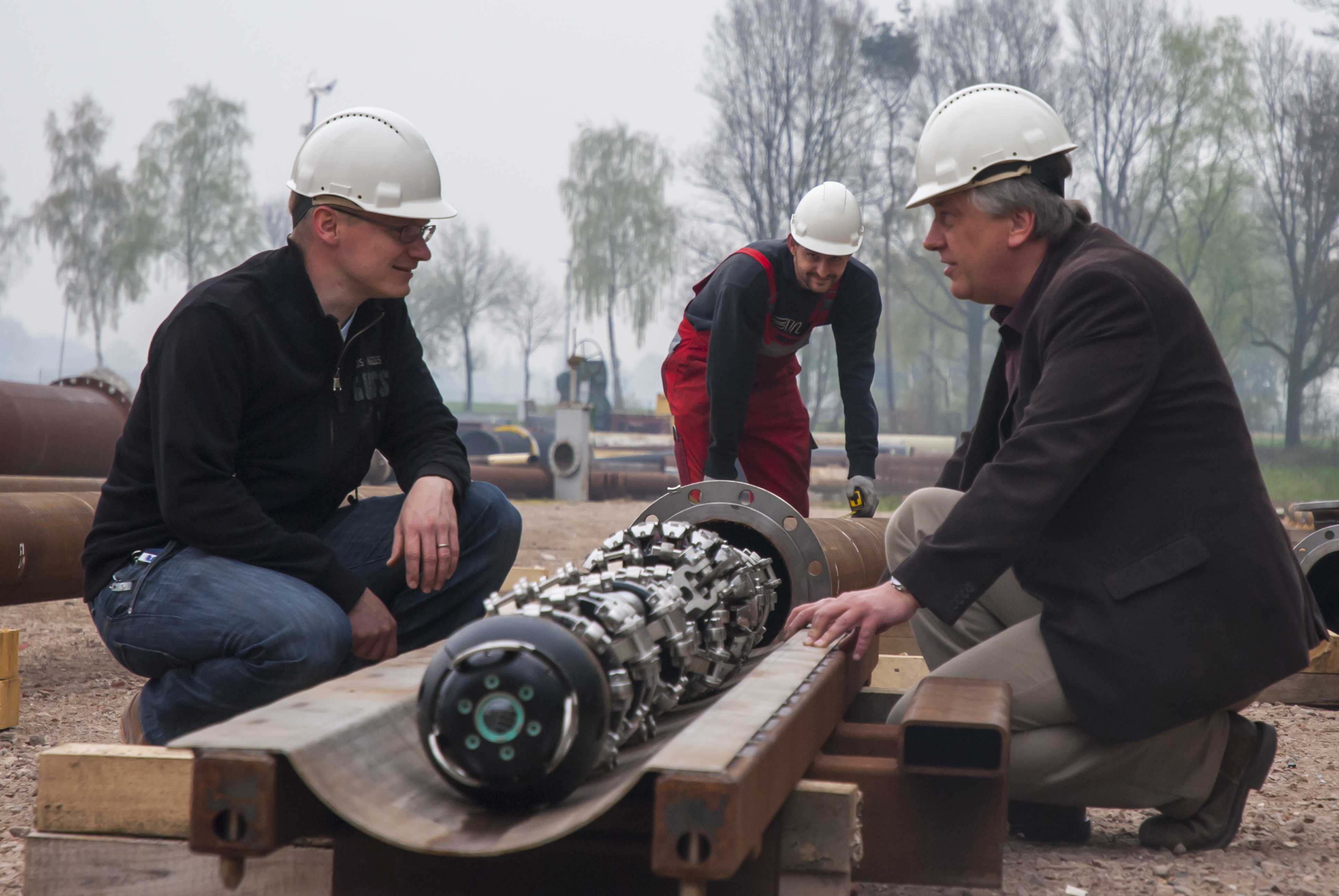
Different categories of internally applied tools, also referred to as “non-traditional ILI” or “specialty free swimming,” are available for challenging pipelines. This term relates to a specialized or modified free swimming ILI tool which can negotiate pipelines with certain geometric restrictions, obstructions or challenges.
Examples may be multi-diameter lines, small-bend radii, certain pipe installations such as wye- or T-pieces, or single-access pipes that require bi-directional tools in order to be launched and received at the same location. Special designs may also have to be used to accommodate special operating conditions, such as low-flow or low-pressure operating conditions.
In addition, there may be benefits to applying a cable-operated or tethered tool, where the cable can be used for energy supply, or data transfer, or simply as an option to pull the tool back to retrieve it. Tethered tools, generally, do not have their own drive and need to be pumped in at least one direction. If pumping or provision of a differential pressure is not feasible, then an inspection device would need its own drive unit. This introduces the realm of crawlers.
The next evolutionary step is robotic tools. These are truly autonomous, not only in the sense of movement but also regarding their ability for making decisions. A simple example would be the ability of the robotic tool to independently recognize the end of a pipe section to be investigated and automatically return to its point of entry.
If access from the inside is not possible and the pipeline is deemed truly unpiggable, a suitable external inspection methodology would have to be applied using external non-destructive testing techniques or the various direct assessment disciplines, such as external corrosion direct assessment (ECDA), internal corrosion direct assessment (ICDA) or stress corrosion cracking direct assessment (SCCDA), providing assessment procedures for metal loss or stress-corrosion features.
A further difference between traditional ILI and the internal inspection solutions for challenging pipelines is that the latter, in most cases, requires individual tailor-made inspection procedures rather than predefined and standardized ones.
Accurate, Reliable Data
The main purpose of any inspection using non-destructive testing technologies is to collect accurate, reliable and robust data about any flaws and defects that may be present in the pipe wall and impair its mechanical integrity. This implies that any device used for the inspection of challenging pipelines must fulfill the same requirements placed on testing piggable pipelines. An anomaly must be detected, sized and located accurately.
Of course, regarding these challenging lines, it must be understood that collecting some data is better than not collecting any data at all. This also relates to the issue of cleaning challenging pipelines. Operational conditions sometimes require a compromise on the inspection technology used.
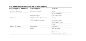
The major types of anomalies an inspection aims to identify are the same for all types of pipelines, as shown in Table 1. As all testing technologies have advantages and disadvantages, it is not sufficient to only have access to one particular methodology. No single inspection methodology will detect, size and identify all the possible anomalies that may be present in the pipe wall. It is important to have the right inspection technology for the job.
In addition to fulfilling certain inspection requirements, the tools used must be able to access the line and reliably travel through it. When addressing challenging pipelines, the issues of accessibility, pipe geometry and operational parameters must be considered.
The creation of an optimized tool implies all aspects of mechanical design, suitable non-destructive testing technology, electronics, storage devices and propulsion means are taken into account, as described by Steinvoorte and Vages (2013). The latter requires access to different propulsion designs in order to provide and ensure maximum traction for a given pipeline environment.
It is important to understand that the inspection of a challenging pipeline requires more than just a specialized tool. It also entails developing and using tailor-made processes for a given inspection task. In other words, it requires an optimized-solution engineering approach. This not only includes the measurement systems, but also the required cleaning and pipeline preparation, as well as tool-tracking procedures.
In summary, it is a matter of using an optimized inspection tool, specialized auxiliary equipment for logging pipeline data or tracking, combined with the correct and effective processes.
A holistic approach implies that a comprehensive range of tangible and intangible resources is necessarry. We call it an “intelligent tool box” approach.
Finding, Sizing Defects
Table 1 shows an overview of the types of flaws that may be present in the steel wall of a pipeline. A comprehensive overview of the potential types of material flaws can be found in the Macaw Defect Atlas (2015).

Table 1: Overview types of anomalies and flaws in pipelines.
In addition leaks must be mentioned, however, really constituting a defect rather than a mere anomaly.
The major non-destructive inspection technologies used by internal pipeline inspection devices are magnetic flux leakage (MFL), ultrasound (UT) and eddy current technology (EC), each coming in a variety of specific applications. For MFL technologies, the direction of magnetization may vary, depending on the type of metal loss to be found, as the aspect ratio of a given feature, i.e. the length to width ratio, has an effect on the sensitivity of the tool used.
In the case of UT, there are different processes on how to induce the ultrasonic signal into the wall to be inspected, such as through piezo-electric transducers, requiring a liquid couplant or electro-magnetic acoustic transmission (usually referred to as EMAT), which can also be applied in a gas environment.
For eddy current there are traditional EC methods, pulsed EC and lately magnetic bias EC. All methods mentioned come with individual characteristics regarding sensitivity to defects and sizing capabilities. Table 2 provides an overview of the technologies often used in traditional ILI.

Table 2: Overview Inspection Technologies applied in ILI tools.
Fully understanding the major strength and weaknesses associated with the non-destructive methodologies mentioned is not a trivial task. Within the context of inspecting challenging pipelines, however, it is important to understand that only access to a wide range of methods will ensure that the most suitable is used to reliably detect, size and identify a given feature.
In Part 2 of this article to be published in the November issue of P&GJ, case studies will demonstrate the issues of accessibility, negotiability and propulsion and show how these proven technologies can apply to a variety of scenarios.


Comments