
June 2018, Vol. 245, No. 6
Features
Examining Data Quality of Robotic Pipeline Inspection Methods
By Paul Monsour, Senior Pipeline Integrity Engineer, Sempra Energy; Francis Gracias, Manager of Data Analysis, Pipetel Technologies; Rod Lee, General Manager, Pipetel Technologies
The robotic pipeline inspection method has been more widely used for integrity assessment of natural gas and liquid product pipelines over the past seven years. While the operational advantages offered by this method may be better known and documented, there is a relatively scarce amount of literature on the quality of data and results acquired by a pipeline inspection robot and the specific threats that can be addressed.
This article examines the ability of robotic pipeline inspection methods to address specific pipeline threats, including surface corrosion, internal and external anomalies, deformations, construction features, and other useful pipeline features and characteristics. Results and specific examples of pipeline anomalies and features found by the Pipetel Explorer robotic pipeline inspection method (that were subsequently excavated and validated) will be discussed. Finally, this article will qualitatively compare the quality of data acquired by conventional free-swimming inline inspection tools with robotic inline inspection tools.
Robotics Inspection
Pipetel Technologies has been inspecting pipelines that cannot be inspected by traditional inline inspection (ILI) tools using the Explorer robotic pipeline inspection systems since 2010. Currently, Pipetel operates a fleet of Explorer robots from 8-inch to 36-inch diameter.
Explorers are tetherless, remotely controlled, self-powered robots capable of inspecting gas pipelines under live pipeline conditions up to 750 psig. Explorers are bidirectional and can travel upstream or downstream under flow or with no flow.
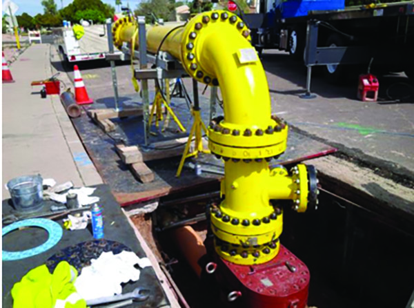
They enter and exit pipes without pre-built traps and receivers through pipe spools mounted on top of industry standard hot tap fittings (Figure 1). Explorers have also entered and exited pipes through conventional pig traps. Since Explorers are wirelessly controlled, they can be stopped to re-inspect any segments or features of interest.
Over the past seven years, Pipetel has inspected pipes with bore reduction up to 75% of outer diameter, vertical segments, mitered-joints, back-to-back elbows, short and long radius elbows, barred or unbarred tees, and valves of various kinds including plug valves.
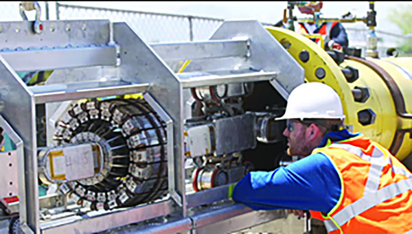
Every Explorer is equipped with high resolution cameras on both ends, a high resolution magnetic flux leakage (MFL) sensor (Figure 2), and a laser deformation sensor. All three datasets are acquired wirelessly and also stored onboard, analyzed and the results included as part of the deliverables.
Unlike conventional ILI tools which travel at the speed of the product flow with some speed control, Explorers travel at a controlled and steady speed of about 4 inches per second (1,200 ft per hour) ensuring the resulting MFL and deformation data is free from any speed excursion and speed related degradation.
For inspections where the point of entry and exit are the same, pipes can be inspected once when travelling away from the point of entry/exit and a second time when traveling back to the point of entry/exit. This results in a redundant set of video, MFL and deformation data for comparison, further analysis and assurance.
Early Adopter
Since the early 2000s, Sempra Energy has been funding the development of Pipetel’s robotic pipeline inspection method through NYSEARCH/Northeast Gas Association. And beginning in 2011, Sempra successfully used the Pipetel Explorer robotic inspection method in a number of its pipelines. The diameter of these pipelines includes 8-, 10-, 12-, 14-, 16-, 20-, 22-, and 24-inch sizes. The length of these pipelines ranges from a few hundred feet to over 2.5 miles.
There are several benefits in using robotic pipeline inspection methods instead of ECDA or hydrotest. First, the cost of assessing a pipeline with an Explorer inspection is more economical. Secondly, many of the pipelines are located in urban and congested areas, environmentally sensitive areas, or other areas such as railways, highways, bridges and river crossings where permitting for ECDA or hydrotesting is difficult.
In some cases, it was simply impossible to gain access to these pipes. For example, a pipeline with a segment under a freeway that Explorer 16/18 successfully inspected, despite the fact that it was deployed from a location far from the highway. The pipeline, built in the 1950s, remained in service at an operating pressure of 375 psi during the inspection.
Finally, an Explorer inspection provides comprehensive data and information about the integrity conditions of the pipeline that allows engineers at Sempra to develop effective maintenance plans.
Pipeline Threats
An Explorer inspection provides data from MFL sensors, a laser deformation sensor (geometry) and videos. The quality of data for interpretation and measurements is similar to that provided by conventional free-swimming ILI inspection data. Similar to MFL sensors on conventional ILI tools, the MFL sensor on an Explorer also measure 360 degrees of the pipe circumference every 0.08 to 0.1 inch axially. The data is correlated with field results. As shown in the examples below, a field picture of external corrosion is shown with the corresponding MFL data.
Seam Weld Corrosion
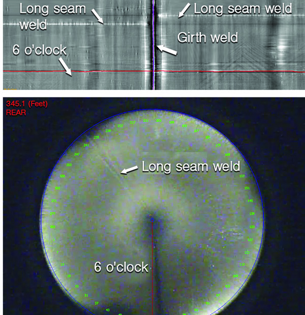
An example of the long seam welds (Figure 3) as seen by the cameras on Explorer and the corresponding MFL data. In this example, the long seam weld on each pipe segment is circumferentially offset from each other across a girth weld. When corrosion threats are present along the long seam weld, they are detected and measured by the MFL sensors.
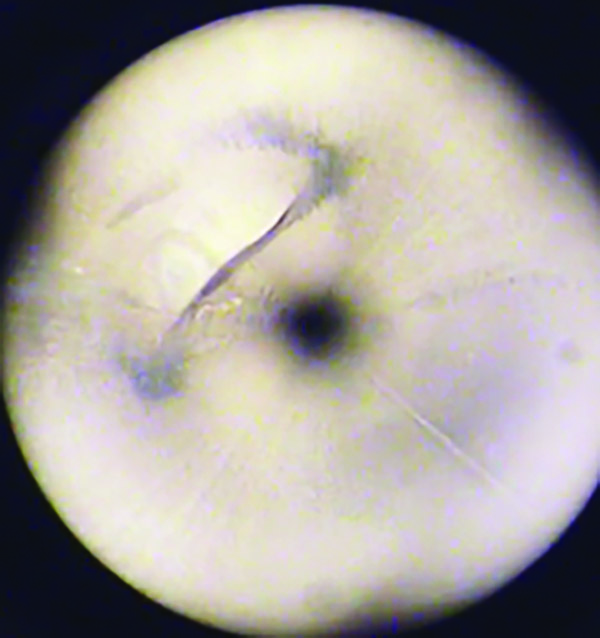
Dents and other third-party damages are often found during an Explorer inspection. Dents can be detected in the MFL, deformation and video data. The dent was about 1% as measured by the MFL and deformation sensor and seen by the cameras on Explorer. In comparison, the dent in (Figure 4) was a 12% dent. Furthermore, metal loss interacting or near a dent is detected in the MFL data. These anomalies are reported such that appropriate remediation can be applied.
Pipeline Characteristics
Seamless pipes: The MFL data depicts a change in pipe type across a girth weld. The pipe segment on the right on side of the girth weld is a seamless pipe whereas the pipe segment on the left is a seam welded pipe.
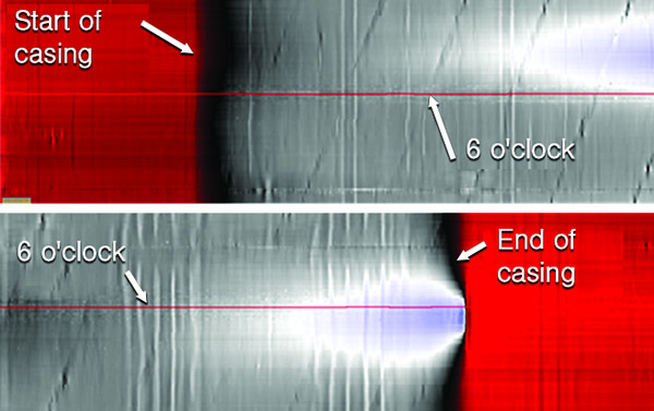
Cased pipes: Similar to a change in wall thickness, the presence of a casing along a pipe segment can also be detected by the MFL sensor on Explorer. As shown in (Figure 5), Explorer located the start and end of a casing. The end of the casing is in contact or closer proximity with the pipe.
Construction Features
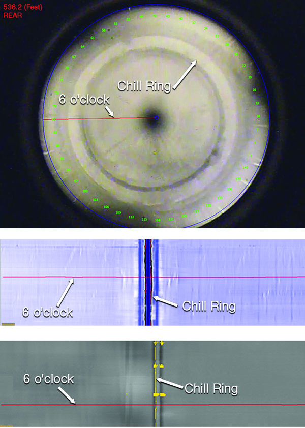
Chill rings: The construction feature in (Figure 6) is a chill ring at a girth weld as seen by the cameras on Explorer. Since Explorer is a robotic ILI system controlled by a Pipetel operator at all times, the Pipetel operator can maneuver Explorer through a chill ring preventing Explorer from getting caught by the chill ring.
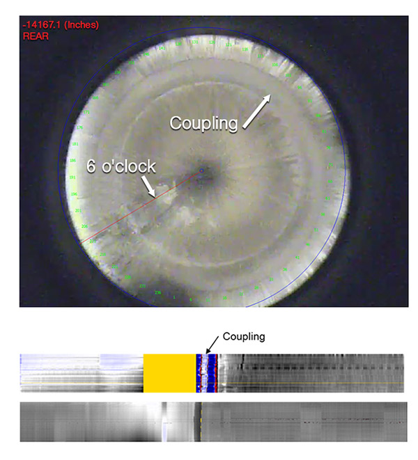
Couplings: When a coupling is detected in a pipeline by Explorer, Pipetel uses the MFL, deformation, and video data to measure the gap, if any, across the two pipes.
This saves the operator from excavating to perform direct measurement (likely using X-ray) on the separation across the two pipes. A coupling across two pipes as seen by the cameras on Explorer. The corresponding MFL and deformation data are used to predict the gap across the two pipes.
Repair patches and sleeves: Explorers have proven to be very effective in finding and locating repair sleeves. Not only do these added metals (typically referred to as metal gains) appear in the MFL data, they can be visualized by the cameras on Explorers (Figure 7).
Heat marks from the welding associated with the repairs are usually visible. Localized patches on a pipe and full-circumferential repair sleeve can be found along a pipe. The added metal from the repair sleeves appears as “metal gain” in the MFL data.
Hot-tap fittings: Unbarred tees and other full bored fittings are regularly encountered by Explorers. An unbarred tee at the 3 or 9 o’clock circumferential location. Tees do not need to be barred for an Explorer inspection.
Pool of liquid of other debris: The video data of a pool of liquid collecting at a low spot along a pipe. An Explorer inspection often uncovers other debris inside a pipe. Liquid collecting at an unexpected location may lead to internal corrosion threats if not remediated. This is yet another piece of information for operators to act upon in safeguarding the operations of pipelines.
Elbows: When Explorers go through an elbow the angle of the elbow was measured and reported allowing the operators to correlate and update their construction records. All Explorers are capable of traversing elbows including short-radius, long radius, and mitered elbows.
Qualitative Comparison
The MFL and deformation sensors on a robotic pipeline inspection system, more specifically an Explorer in this case, are competitive or even better than those found on conventional ILI tools. The MFL sensors are capable of fully saturating or magnetizing the pipe materials up to the maximum wall thickness capability of the sensors.
They offer similar or even better axial sampling frequency and circumferential sensor spacing as conventional ILI tools. The resulting MFL data from an Explorer inspection offers the distinct advantage of being free from any speed related degradation which commonly exists in conventional ILI. This is because Explorers travel at a relatively slow speed of 4 inches per second and the speed remains constant despite the flow and pressure conditions inside the pipes.
In conventional ILI, degradation of data often takes place in gas pipelines due to speed. During launch, after an elbow or a change in wall thickness, due to the compressibility of gas, pressure behind the ILI tools must build up for propulsion resulting in high acceleration of the ILI tools and subsequently degradation of data. Explorers are free from these compromises and will almost always provide excellent speed profiles well below 1 meter per second.
The deformation sensor on Explorers also offers superior circumferential resolution compared to conventional ILI tools. While the resolution of the deformation sensor on any conventional ILI tools is limited by the sensor spacing of each mechanical sensor, the resolution of the deformation sensor on Explorer is continuous since a laser is used without any discrete spacing.
The circumferential resolution of the laser ring is not limited by any physical sensor spacing. Not only does this allow Pipetel to accurately measure dents and other deformations, it allows for higher resolution and accuracy of subsequent dent strain analysis should the operator choose to perform such analysis.
Finally, as seen throughout this paper, the MFL and deformation data are always supported by visual evidence captured by cameras. This evidence provides added certainties and reveals new information about a pipe.
Conclusions
An Explorer robotic inspection provides a comprehensive data set from a pipeline. This article provided many examples of threats, features and other information commonly found in an Explorer inspection.
More importantly, the amount of information and knowledge returned from an Explorer inspection provides a holistic view on the status and conditions of a pipeline for operators to develop actionable plans to maintain the safe operations of their pipelines.
The MFL and deformation sensors are at least comparable, if not superior, to those found on conventional ILI tools. Robotic inline inspection method is conducted at a controlled, steady and relatively slow speed, and is therefore completely exempted from any degradation of data quality due to speed related compromises. Together with the ability to see inside each pipe, robotic pipeline inspection method is setting a new and elevated standard in inline inspection of pipelines. P&GJ
Editor’s notes: The sample data and figures related to the Pipeline Threats section are not from Sempra projects. Content is partially reproduced from a version published at the Clarion Unpiggable Pipeline Solutions Forum 2017.

Comments