
August 2021, Vol. 248, No. 8
Features
Challenges of Installing a New Pipeline
By Eric S. Langelund, Piping & Corrosion Specialties and Kimberly-Joy Harris, Enbridge Energy
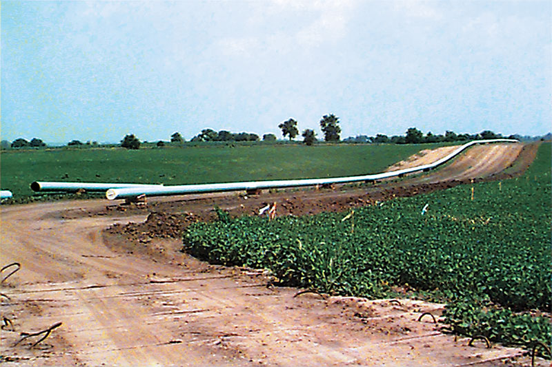
Each year hundreds of miles of pipeline are installed. During the installation of a new pipeline, corrosion engineers must consider many different aspects of the pipeline and its corrosion protection. On the surface it may appear simple, thinking only of coatings and cathodic protection (CP), but once construction is underway, the tasks are many.
Pipeline installation is accomplished through the efforts of multiple teams of personnel, all of whom have their own duties and concerns. Safety, transportation, materials, equipment and construction are some major components of pipeline installation.
Corrosion engineers must address all of these areas to ensure the corrosion protection system is installed and functioning to meet the requirements of federal, state and local regulatory agencies as well as the company’s requisites and timelines.
Pipeline Coating
The coating is the first line of defense against pipeline corrosion, and most pipelines are coated. Selecting a coating system that is appropriate for the right-of-way (ROW) conditions is very important. Some coatings are petroleum-based and may not be suitable for soils with existing hydrocarbons.
Other coatings are pliable and are ideal for filling voids along the surface of the pipe, but they are not compatible with clay soils that exert stresses onto the coating. If the ROW environment is rocky, a thicker coating may be preferred. If the ROW requires horizontal directional drilling to install a pipeline underneath a river or other obstacle, a thick, abrasion-resistant overcoat may be selected.
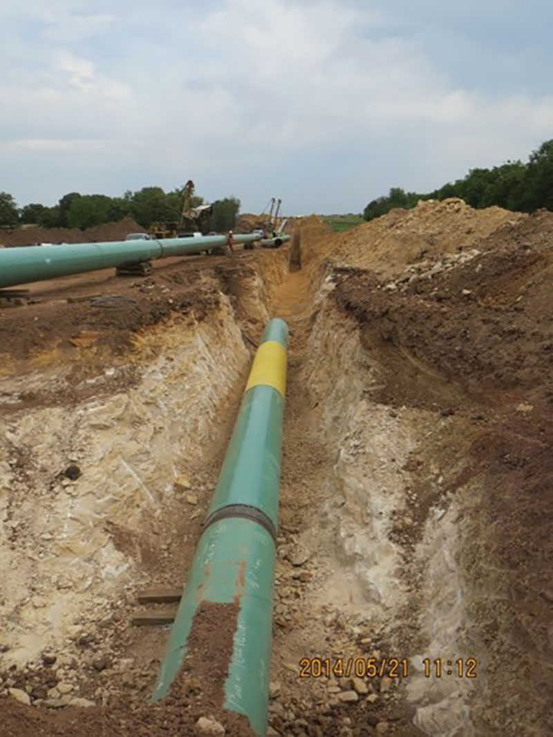
Common coatings used for cross-country pipelines are fusion-bonded epoxy or two-part epoxy coatings with a standard layer that measures from 19- to 24-mils (482- to 610-µm) thick. Once a coating is selected, it is recommended that the pipe coating process is inspected at the mill. This helps to ensure the surface is properly prepared and the pipe is handled appropriately.
During pipeline installation, welded joints must be coated in the field. It is crucial to select a coating that is compatible with the mill coating and use in the field. Inspecting the application of the field coating at the pipeline joints is important as well.
This ensures that the appropriate surface preparation, pipe preheating (if necessary) and specified coating application is taking place. Additionally, the joint coating should be tested for holidays (i.e., coating flaws) and repaired if necessary.
Cathodic Protection
The CP system is the second line of defense for protecting the pipeline from corroding. Although most pipelines have an effective coating, the CP system is essential for protecting areas of the pipeline where the coating has a holiday or may be deteriorating. Since the demand put on the CP system is determined by the coating quality, the condition of the coating should be the best it can be when the pipe is installed.
Many factors are involved when designing the CP system for a new pipeline. Apart from the actual current calculations, environmental conditions along the ROW also must be addressed. Many new pipelines will cover a lot of terrain with varying soil types. Supplemental CP may be required in areas where the soil has high resistivity.
CP designs for new pipelines must consider any existing CP systems for other nearby pipelines (known as foreign pipelines). In some instances, there isn’t an easy way to establish an electrical bond between pipelines. This means the CP system for the newly installed pipeline would need to overcome the influence of any other CP system.
The first thing to review for CP of a new pipeline installation is whether there are foreign pipelines crossing the new pipeline’s route, or ROW. Existing pipelines in the ROW of the new pipeline can pose many obstacles when designing a CP system. New pipelines in crossings may experience interference from stray current – which is current from another voltage source, such as a CP system for a nearby foreign pipeline or current from an adjacent electrified railway – or shielding of CP currents.
Often, the extent of stray current interference is unknown until the new pipeline is fully installed. CP design allowances for pipeline crossings and stray current interference should be made, as much as possible, on the front end of a project.
Stray Current
CP systems from foreign pipelines can cause depressed structure-to-electrolyte (S/E) potentials (i.e., potential readings are more electro-positive than the accepted criterion of –850 mV vs. a copper/copper sulfate [Cu/CuSO4] reference electrode) for the newly installed pipeline. In this case, the electrical current picked up by the affected pipeline will be discharged from that same pipeline.
The discharge site on the affected pipeline is where the depressed S/E potentials appear and where corrosion occurs. One way to mitigate this interference is to establish an electrical bond between the newly installed pipeline and foreign pipeline. The bond provides a path that allows electrical current involuntarily picked up on the affected pipeline to be returned to the pipeline with the CP source.
Most operators and the corrosion consultants who support them participate in regional electrolysis committees that meet periodically to set up pipeline interference tests to determine the impact, if any, of a pipeline’s CP system on other cathodically protected structures in the vicinity.
Another way to address stray current interference is to install supplemental CP at the current discharge location on the affected pipeline. This often involves installing sacrificial anodes so that the current discharge takes place at the anodes instead of the affected pipeline’s surface. There are many configurations for this type of stray current mitigation.
Stray current interference can also originate from rail systems powered by direct current (DC). The DC used to power the trains inadvertently leaks into the earth. The current then finds the path of least resistance back to its source. Often, this path is a nearby pipeline. Where the current is picked up on the pipeline, there is free CP for the pipe.
However, corrosion occurs where the current is discharged from the pipe. For a carbon steel pipeline, 1 amp of DC current over the course of a year takes about 20 pounds (9 kg) of iron with it. Mitigation of stray current under these conditions may involve an electrical bond back to the rail power source or the installation of supplemental CP.
Within the last 30 years, induced alternating current (AC) voltage has been identified as a pipeline safety concern. Pipelines that parallel overhead high-voltage AC (HVAC) transmission lines pick up induced AC voltage from the magnetic fields produced by the overhead wires.
The induced AC voltage has been found to be dangerous to field personnel, and NACE International set a safe limit of 15 VAC. When testing pipelines beneath HVAC transmission lines, it is recommended to measure and record the AC voltage of the pipe in addition to the S/E potential.
Where pipelines exceed 15 VAC, grounding mitigation is recommended, such as grounding mats at test stations and valves where personnel come into contact with the pipe, or linear grounding along the length of a pipeline where it is positioned beneath HVAC transmission lines.

Such grounding is typically connected to the pipeline through an electrical isolation device, which conducts AC to effectively ground and discharge the induced AC voltage and block DC voltage, so the CP system is not adversely affected. The magnitude of induced AC voltage is based on many factors, including distance between the pipeline and the HVAC transmission line towers, routing of the pipeline, number of HVAC transmission lines and pipeline coating system. Typically, the AC voltage is higher where the pipeline enters and leaves the power corridor.
More recently, induced AC voltage has been found to cause AC corrosion, which is due to improved pipeline coatings. This phenomenon is the result of induced AC voltage being discharged from the pipeline surface at a coating holiday. The effect of large AC current being discharged from a small, focused holiday location can result in aggressive corrosion.
This corrosion is so destructive that there have been instances in which a pipe has experienced through-wall penetrations in a matter of months. Soil resistivity, induced AC voltage and AC current density are all factors that influence AC corrosion. Identification and mitigation of AC corrosion is imperative. Coupon test stations and remote monitoring are good tools in areas where AC corrosion may be a concern.
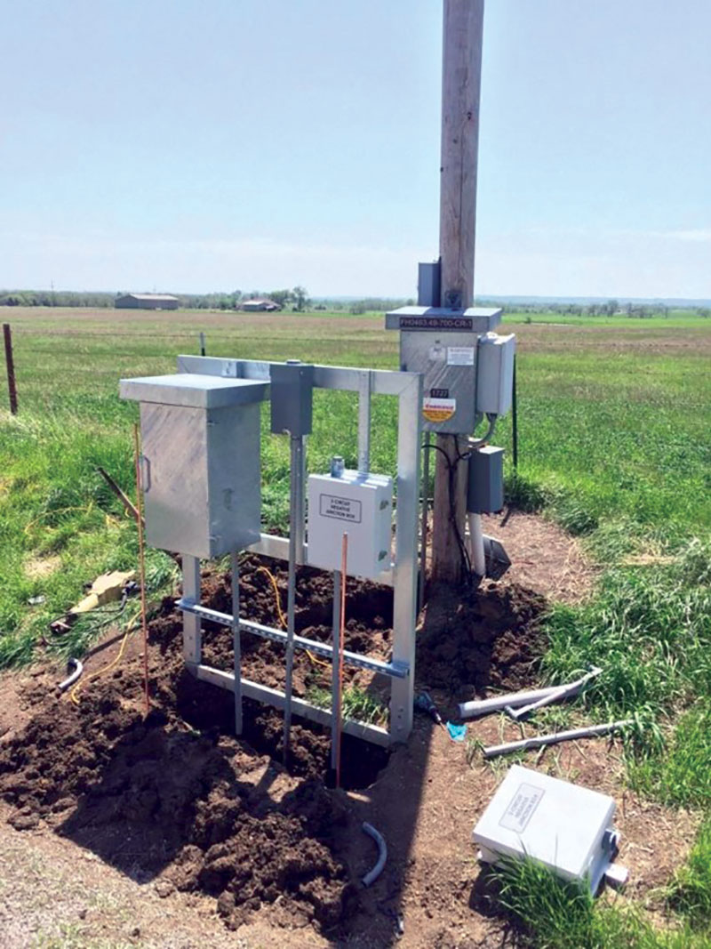
Test Stations
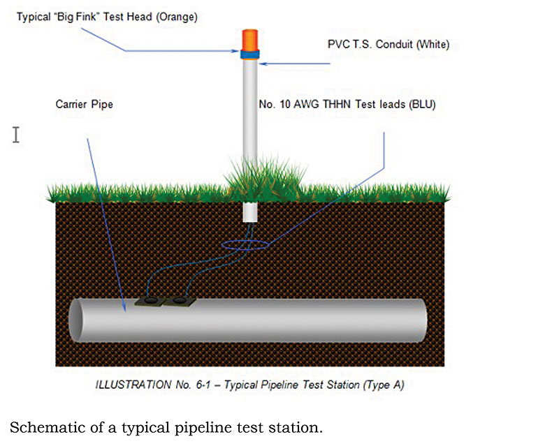
Test stations are used to measure S/E potentials so the effectiveness of the CP system can be monitored and evaluated. Although there are different types of test stations with different materials of construction, their purpose is the same.
They simply house test lead wires that are connected to a buried pipeline to provide an easy connection to the pipe for testing the CP system. The best time to install test stations is when the pipeline is being installed. Test lead wires (normally two) are attached to the buried pipeline and routed up to grade into a protective housing (test station).
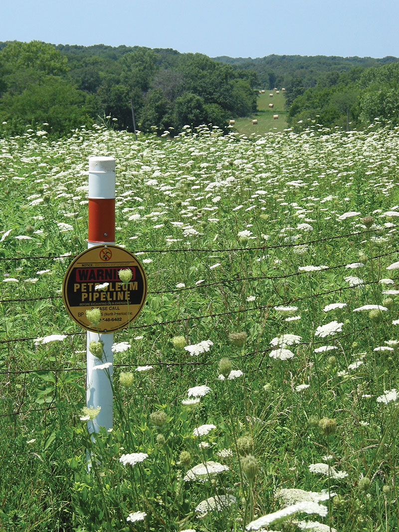
Selecting the proper locations for test stations is important. Typically, test stations are installed at each road crossing as the pipeline is routed from Point A to Point B. Additional test stations are often placed at fence lines when there is a large distance between roads, at or near crossings with foreign pipelines and at any other location identified as a concern for the effectiveness of the CP system. Typically, one test station is installed every mile along a pipeline.
A permanent reference electrode may be buried near the pipeline to provide good earth contact for measuring S/E potentials in an area where soil conditions for measuring S/E potentials are not ideal (e.g., the ground is very dry, susceptible to freezing or covered with asphalt or concrete). The permanent reference electrode test lead wire is routed into and terminated within the test station with the other pipe wires.
Where stray currents or poor soil conditions exist, a test station with coupons may be installed. A coupon is a small, metal sample that is installed adjacent to the pipeline that represents a holiday in the pipe coating. Ideally, the coupon size is selected based on estimations to represent the worst-case holiday on the pipeline. The S/E potentials of the coupon are used to evaluate the effectiveness of the CP system, with the theory being that if the coupon is being protected by the CP system, so is the pipeline.
Since foreign pipeline crossings can result in stray current interference between pipelines, test stations with test lead wires on all pipelines should be installed at foreign pipeline crossings to allow comprehensive testing of all pipes. This would include interference testing to ensure that one pipeline’s CP system is not hindering the effectiveness of the other pipeline’s CP system. Test stations at foreign pipeline crossings often include permanent reference electrodes and coupons to facilitate thorough testing of the pipes at pipe depth.
A bond may be established between pipelines to alleviate the influence of one CP system on another, and so it is advisable to install a larger cable on the new pipeline during construction and route it into a nearby test station. If interference is found, the new pipe will already have a suitable bond cable installed, which makes the process of establishing an electrical bond easier and more cost-effective.
Cased Crossings
As a pipeline is routed from Point A to Point B, it will cross many obstacles along the way, such as roads, rivers, railroads, foreign pipelines, etc. Depending on local regulatory requirements, some of these crossings may require the installation of a casing pipe for the carrier pipe to pass through, although it may not be desirable. Casing pipes are avoided for several reasons.
A casing pipe may come into contact with the carrier pipe and short out the carrier pipe’s CP system, which would result in low pipe potentials in the vicinity of the casing and the absence of CP for the carrier pipe within the casing pipe. Because a casing pipe can become filled with ground water, although very likely, an electrolytic short between the casing pipe and carrier pipe can occur.
This also results in low pipe potentials in the vicinity of the casing. Recent construction practices tend to avoid casings wherever possible and may include techniques such as horizontal directional drilling to lay a pipe at a greater depth below an obstacle.
Should the installation of a casing pipe be unavoidable, several practices can help protect the carrier pipe. Casing spacers should be used to support the carrier pipe within the casing pipe to ensure that there is no direct contact between the pipes. The appropriate number of spacers for the carrier pipe diameter should be installed, and the spacers should be made of a suitable dielectric material to electrically isolate the pipes from one another.
Sealing the ends of a casing may be desired to help keep water out of the casing and contain vapor corrosion inhibitors (VCIs) within the annular space between the carrier pipe and the casing pipe. Nowadays, many operators are using VCIs in the annular space.
The vapors provide corrosion protection and some VCIs raise the pH of the annular space to further reduce corrosion. Pumping dielectric wax into the annular space between the carrier and casing pipes is an alternative that can help keep water out of the casing. The wax displaces any water and provides a nonconductive environment around the carrier pipe.
Prior to installing sealing materials at the ends of the casing, any debris inside the casing pipe should be removed. Sealing the ends of the casing may include rubber links or boots that squeeze between the pipes or clamp around the pipes. Metallic bolts or banding should not come into contact with both pipes. Some sealants used to close the ends of the casing are non-metallic and may be used in conjunction with other systems.
Test lead wires should be installed on both the carrier pipe and casing pipe. During backfilling of the pipes, care should be taken to ensure the lead wires are protected and do not come into contact with both pipes. Many electrical shorts between the carrier pipe and casing are the result of the lead wires coming into contact with both pipes during the backfill process.
It is recommended that two lead wires be connected to each pipe at both ends of the casing. Advanced troubleshooting of casing shorts would require the additional wires, which are much easier to install during pipeline construction. Installing permanent reference electrodes at casing pipes is recommended, because the pipe is often much deeper than normal at these locations.
Because of the many issues related to designing a pipeline CP system, company standards for CP engineering and design should be established. The company standards should call for written specifications for approved materials and detailed drawings depicting approved installation practices.
Written specifications should spell out the coatings, test stations, anodes, etc. that are approved for use. They also should address design requirements so stray current interference or induced AC voltage are not overlooked during pipeline installation.
Detailed drawings should depict approved installation methods of CP system components. They should be detailed enough to prevent improper or incomplete installation of test stations, anodes, pipeline coating, etc.
This article is based on CORROSION 2017 paper no. 8947, “Pipeline New Construction Challenges,” by E.S. Langelund and K.-J. Harris.
Authors: Eric S. Langelund is a project engineer with Piping & Corrosion Specialties, Inc., Millersville, Md. He is a corrosion control consultant specializing in cathodic protection system testing, troubleshooting, design and installation. He has been a NACE International member for more than 28 years. He holds a bachelor’s degree in materials engineering from the University of Wisconsin, Milwaukee.
Kimberly-Joy Harris is with Pipeline Integrity Services at Enbridge Pipelines, Edmonton, Alberta, Canada. She specializes in external/internal corrosion control design, monitoring and inspection for onshore/offshore pipelines and above-grade tanks; pipeline corrosion integrity management; and coating materials selection and inspection. Harris holds a master’s degree in instructional/organizational leadership and a Ph.D. in physics. She has been a NACE International member for 29 years.
This article was originally published in the February 2018 issue of Materials Performance and reprinted with permission.

Comments