July 2021, Vol. 248, No. 7
Features
Reassessing Value Placed on System Pressure Tests
By Alan Gillen, JIP Committee Chairman, Pipeline Delivery Manager at Woodside Energy, Olivier Royet, JIP Team Member, Senior Specialist at DNV and Harald A. Wathne, JIP Project Sponsor, Head of Section at DNV
Since the cost of failures during the construction of offshore pipelines is significant, over time, an extensive quality management regime has been developed. One such measure is to pressure test the whole pipeline system when the build is completed.

This will prove that the pipelines have been constructed without any leakage. On the other hand, such a test involves other safety and environmental risks for the project. It is therefore important to reassess if the procedure is justified and brings added value.
For instance, because pipe mills now produce high-quality pipeline steel and welds that are practically flawless, the value of the system pressure test (SPT) is reduced, as it mostly serves as a post-installation system check for contractual purposes. Similarly, the quality assurance (QA) and quality control (QC) of girth welds have been enhanced on lay barges through the automated welding process and inspection technique.
In 1996, DNV rules for submarine pipeline systems allowed for waiving the SPT based on compliance with some specific requirements. This was the case for the Gulf of Aqaba Pipeline in the Middle East, shortly followed by the Cameron Highway Oil Pipeline for GulfTerra in Texas and, more recently, the Turkstream project, a new export gas pipeline stretching from Russia to Turkey across the Black Sea. For these projects, the replacement was successful, and the pipelines are now in normal operation.
To challenge the relevance of the SPT, DNV, the global independent expert in risk management and quality assurance, spearheaded the Replace Joint Industry Project (JIP), which kicked off in 2019.
With a total of 21 participants, the collaborative initiative reflected all parts of the value chain, from engineering consultants, pipe mills and installation contractors to operators and five national regulatory authorities. The objective was to develop and issue a guideline detailing a systematic approach to enable participants to repl ace the SPT for selected pipelines with “extraordinary disadvantages” related to the SPT.
Benefits, Drawbacks
Pressure testing regimes were introduced nearly a century ago in 1926 as part of the American Society of Mechanical Engineers (ASME) pipeline code and were used to carry out a mill pressure test of each pipe joint to 90% of the yield stress, limiting the pipeline operational pressure to 80% and giving a utilization factor of 0.72.
After a series of onshore pipeline incidents in the 1950s, the SPT was introduced as an additional pressure test of the assembled pipeline. This led to detection of leaks caused by errors made, such as transportation damage, girth weld defect and post-installation damage.
As the oil and gas industry ventured offshore and into deeper and more hazardous environments, the focus of the SPT moved from detecting defects toward preventing them. The focus on QA and QC throughout the construction processes also increased. Thus, the value of the SPT has changed.
The main advantage of the SPT is that it is universally accepted by the industry and provides evidence of final system assembly completion, i.e., a contractual obligation. This must be compared with the disadvantages, which includes the following:
- Safety risk exposure of personnel carrying out the SPT
- Environmental impact of chemicals associated with water treatment and their discharge after testing
- Possible integrity risk related to internal corrosion due to test water
- Increased schedule of test activities for some pipelines, particularly for longer and larger gas pipelines
For long and large pipelines in particular, the sensitivity of the SPT over a 24-hour holding period is limited to large defects because smaller leaks can be difficult to detect.
This can vary as a result of test fluid compressibility and pressure effects, which are impacted by the length of the pipeline, a large range of water depths and temperature variations. One could extend the test period to mitigate this disadvantage.
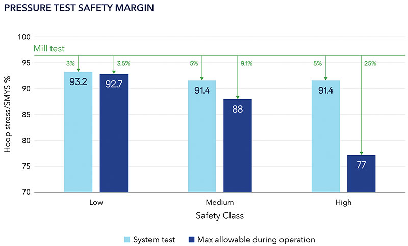
The stress induced by the SPT into the pipeline varies slightly between different international pipeline codes. In DNVGL-ST-F101, the highest mill test pressure experienced by the line pipe is reaching 96% of the specified minimum yield stress (SMYS). Figure 1 shows the hoop stress level in the pipe wall comparing the mill pressure test, the SPT and the operational state for the three code safety classes.
As seen in Figure 1, the margin between mill test pressure and incidental pressure increase, ranging from 3.5% to 25% from safety class low to safety class high.
While it could be inferred that carrying out an SPT is more beneficial than not performing one, it is expected to be the standard practice for many years to come. SPT, as a gross error test in an industry driven by quality and excellence, the decision to replace the SPT for an offshore pipeline system is likely to impact many aspects of the project.
Collective Insight
Section 5.2.2.3 of DNVGL-ST-F101:2017 permits replacement of the SPT “for pipelines where the disadvantages with the system pressure test are extraordinary” and states that alternative means shall be agreed upon to ensure the same level of integrity is maintained as if the SPT were undertaken.
With the advent of longer, larger and deeper water pipelines, “extraordinary disadvantages” of the SPT were becoming more prevalent in the industry. Hence, the objective of the Replace JIP was to provide more concrete guidance and formulate an approach to replace the SPT. Initially, a series of face-to-face workshops took place, which were moved online in adherence with COVID-19 restrictions.
One of the first tasks was to collect and review a description of SPT failures to identify the failure mechanisms and the associated root causes. The work also included a review of literature exploring replacement of the SPT. While most of this research discussed the possibility for weld defects developing into rupture, no such failures have been found for offshore pipelines for the last 30 years.
The JIP participants also contributed with anonymized experiences. To complete the database, near misses that could have been discovered by the SPT were also recorded. Among the 46 cases reviewed, covering a period from 1976 to 2019, the identified leaks were categorized by type:
- Mechanical leak, defined as a leak path between two subassemblies, such as a flange and seal.
- Material failure, defined as a leak path through a material existing from manufacturing.
- Damage introduced during subsequent project phase such as installation overload and external damage to the pipeline.
Quality improvements in materials eliminated most of the historical failure mechanisms. Looking back at 17 failures that occurred in the previous 10 years, it was observed that 70% of the cases were associated with mechanical couplings.
The remaining failure cases were related to external damage post-installation, such as trenching and rock placement. One near miss was detected due to delayed hydrogen cracking, detected at the submerged arc welding steel pipe (SAW) pipe mill during a code-mandated inspection.
Mitigating Leak Risk
Each case was reviewed against the current general code requirements (DNVGL-ST-F101:2017) to assess if a similar failure could develop considering adequate code and quality management processes. It was concluded that all the cases would have been detected or mitigated by one or several current code requirements.
For each case, the pipeline system key parameters were identified, such as date, line pipe manufacturing method, material grade, installation method, post-installation interventions, mechanical connection, etc.
While these details were not available for all cases, the objective was to identify the failing component and associated failure modes. Once all the failure modes were defined, the cases were reviewed to identify commonality within each failure mechanism.
The current requirements of DNVGL-ST-F101 are intended to avoid these failure mechanisms. These requirements were reassessed, formalized and detailed in the JIP guideline into prerequisites, requisites and additional safeguards with the purpose of identifying common parameters that, if omitted, could avoid such failures:
n Prerequisites: Requirements to the pipeline design that shall be met. These exclude pipelines that do not have a good track record as identified during the JIP failure review.
n Requisites: Requirements mostly linked to QA and QC that shall be met. Some of these will exclude pipelines that do not have a good track record, and some will be reflected in the Replace Plan
n Additional Safeguards: Based on JIP-specific Failure Mode, Effects & Criticality Analysis (FMECA), mitigation measures shall be identified and implemented. These will constitute the main part of the Replace plan.
n Alignment with existing clauses was mostly confirmed but with some additional requirements, such as the inclusion of line pipe production process, use of automated ultrasonic testing (AUT) for girth welds and the potential of using corrosion-resistance alloy (CRA)-lined and cladded line pipe.
Replace Plan
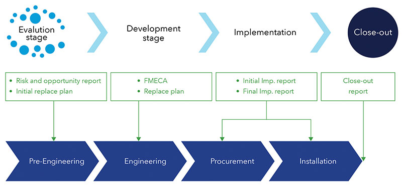
The SPT is part of what is referred to as “pre-commissioning” and this phase also includes other activities (Figure 2).
Since water filling of the pipeline for a SPT is not required, other activities such as dewatering and drying become redundant or may become redundant, while others such as cleaning and gauging must be modified.
This is recognized in DNV-ST-F101, which recommends that: “…a systematic approach and the risk assessment shall lead to a technical assurance program that is implemented and followed up in all relevant phases.” A review of such alternatives and proposals also has been included in the JIP guideline.
Although the SPT is performed as part of pre-commissioning at the end of a pipeline development project, the Replace methodology must be considered as early as possible, as described in the following:
Evaluation stage – Review the prerequisites and perform a risk and opportunity assessment to allow for a first assessment of the design suitability.
Development stage – A FMECA will be performed to identify project-specific mitigation measures. Together with the prerequisites and requisites, the additional safeguards will lead to a set of quality management activities to be implemented into the Replace plan covering project design, procurement, installation and pre-commissioning.
Implementation stage – Ensure that the plan is monitored and documented continuously as part of normal project quality management. Change management shall be implemented to ensure the plan is followed.
Close-out stage – Confirm the successful implementation of the plan up to the completion of subsea installation activities, i.e., pipeline installation and seabed intervention.
Confirmation stage – A third party must follow the process and issue a statement of conformity stating that an SPT is not required (Figure 3).
Future Expectations
The SPT continues to be viewed as the ideal test for gross error leakage detection and is expected to be used as standard practice for many years to come. However, for some specific projects where the disadvantages of the SPT are extraordinary, the Replace methodology may be an alternative. Primary candidates are long, large, deep, dry gas pipelines.
In the future, it also may be considered where challenges are linked to the water required for the SPT, either due to lack of access to water (on dry land) or freezing of water (Arctic pipelines).
While the Replace guideline is currently confidential to the sponsors, it will most likely be made public in a Recommended Practice (RP) after the two-year confidentiality period.
In the meantime, JIP participants will continue to feedback learning from using the guideline to DNV and the JIP participants. The Replace methodology is already being applied to various major projects around the world.
Authors: Alan Gillen is a pipeline delivery manager for Woodside Energy and is a Charted Engineer in both the U.K. and Australia. He has worked in Europe, North Africa, Southeast Asia and Australia, and has more than 30 years’ experience in the offshore industry covering design, construction and operations of pipelines and subsea infrastructure.
Olivier Royet is a senior principal specialist based in Perth, looking after subsea and pipeline projects in Australia. As a technical lead for design, fabrication and installation verification, he is involved in installation packages covering subsea, risers, flowlines and trunkline packages. He is a member of Australian standard committee for ME-92, AS 2885.3 and AS 2885.4.
Harald A. Wathne is head of the pipeline technology section located at Høvik, Norway. The section is responsible for the DNV-ST-F101 and about 20 related recommended practices covering the offshore pipeline systems. With a structural engineering background, he has worked with design, R&D and installation of pipelines for 15 years.


Comments