
March 2021, Vol. 248, No. 3
Features
Life Extension of Pipelines with Crack Defects Using Composite Repairs
By Troy Swankie, DNV, and Paul Hill, Team Industrial Services Inc.
Composite repairs are being used widely to restore the integrity of pipelines impaired by wall thinning arising from corrosion anomalies.
The international standards ASME PCC-2 Article 401 and ISO 24817 have been adopted to guide such applications and have facilitated the wide growth in acceptance of the approach. Industry test programs, such as those by PRCI at Stress Engineering Services, Inc. (SES) in the US, have provided further support for the technique.
As experience with composite repairs has grown, so has the understanding of their strengths and weaknesses.1 There is growing interest in using them to extend the service life of pipelines containing crack-like defects. Defects, such as those caused by stress-corrosion mechanisms and arising from manufacture has generated interest.
Defects in both girth and seam welds on vintage pipelines are also of interest as repairing these could defer or even obviate the need for replacement and lead to significant cost savings whilst not compromising operational safety.
Conventional vs. Composite
Traditional repair methods such as the installation of a welded steel sleeves are not always simple to fit particularly, where there are unique geometries and out-of-roundness. Composite repairs are generally installed without requiring any hot work, plus the wet lay-up systems can be applied to a full range of geometries without incurring significant delays.

A study in 20192 of pipe ranging in diameter from 8 to 22 inches looked at planar defects in the seam weld of low-frequency, electric resistance welded (LF-ERW) pipe. Pressure cycle fatigue testing was completed on modern pipes with defects simulated using electric discharge machined (EDM) notches as well on vintage LF-ERW samples removed from service.
Application of the composite repairs significantly increased the measured number of cycles to failure of the test samples. A large amount of scatter was noted in the results, but the general trend matched the expectation that reducing both the maximum strain and the strain range within the notch extends the fatigue life of the line.
As a general conclusion, stiffer repair systems utilizing carbon-fiber reinforcement gave the greatest extension in fatigue life, although systems using very high stiffness fibers did not always perform as well as expected. It was concluded that carbon fiber reinforced repair systems would extend the fatigue lives of cracked lines when correctly applied.
The results also demonstrate that a qualification test program should be completed by each repair system to confirm it delivers the performance expected. Separate work reviewed the results from the SES program to predict measured performance.

It was further ascertained that installing a composite repair will never stop crack growth entirely and that life extension is dependent on the following factors:
- The pressure and temperature in the line at time of installation
- The cyclic pressure and cyclic thermal loading
- The details of the repair installed (thickness and mechanical properties)
- The properties of the original pipeline.
With the understanding of the interaction between the steel pipeline with the repair and the resulting change in crack growth rates having reached the stage where modelling and testing align closely, it gave support to the concept of installing the repairs on pipelines in service.
Case Study
During routine re-painting work on an 18-inch natural gas line, a large colony of circumferentially oriented crack-like defects were found on the extrados of a field bend on an above ground section of the line.
The area affected extended approximately 1.4 meters around the apex of the bend and 460 mm around the pipe circumference. The longest individual feature was 30 mm in length. The cracks were located at least 890 mm from the nearest girth weld.
An assessment was completed to determine the remaining life of the line and recommended actions needed to allow the pipe to remain safely in service. The morphology and orientation of the features (irregular surface profile and relatively wide opening) are characteristic of ductile tearing.
The investigation concluded that the defects were likely to have been caused during construction. The large number and proximity of the defects meant that it was not possible to measure the individual depths for each of them.
Given these features had probably been present since construction it was proposed that they will have all survived the original hydrotest of the line on commissioning. On this basis, a fracture mechanics assessment was undertaken to determine whether defects that would have just survived the hydrostatic pressure test on commissioning would have the potential to grow under normal pipeline operating conditions. The analysis also considered environmental conditions through historical temperature profiles obtained from the U.K. Met Office.
Due to the uncertainties with the input parameters for the analysis it was not possible to rule out the potential for growth of those defects that would have just survived the hydrotest. Consequently, it was decided that the pipeline should be repaired.
Cut out and replace and steel-shell repair options were considered but would have been difficult to implement. As it was not desirable to isolate the line or install a bypass to facilitate cutting out, in addition to the weight and practicality of installing a steel shell, it was not a favored option. A composite repair was considered simple to install but additional engineering support was required to justify its use.
Composite Selection
The composite repair system proposed was an ambient temperature curing, carbon fiber-reinforced repair system, qualified in accordance with requirements of ISO 24817 and ASME PCC-2 Article 40. The system has strength in both the hoop and axial directions, which was considered important given the orientation of the cracks in the bend.
An initial repair thickness was selected based on reducing the stress in the steel line to a target level; a thickness of 10.8 mm (0.425 inch) was proposed (equivalent to ten layers of the repair material). The repair was to extend a minimum of 100 mm beyond the defect area at both ends. An additional repair length was specified to accommodate biaxial strain gauges that were used to measure the reduction in strain in the line due to the repair.
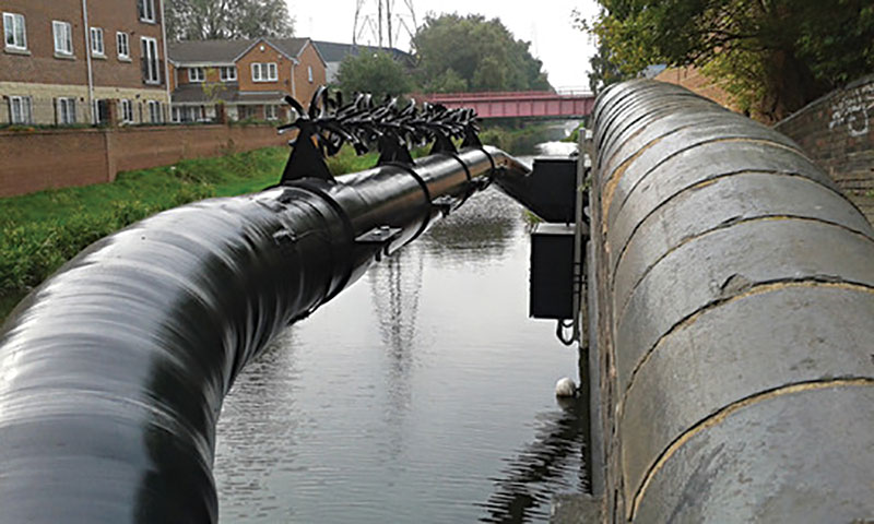
The strain gauges were configured to measure principal strain as a conservative output. As can be seen in Figure 1, they were installed in pairs, but offset axially along the pipe with one gauge positioned under the repair and the other just outside.
Comparison of each pair of strain gauges enabled the effect of the repair to be isolated and fatigue life to be quantified. The repairs were installed with the pressure in the pipe reduced to 2bar to maximize the load transferred from the pipe to the repair (Figure 2).
Assessment of Repair
The data was recorded for 350 days. Consistent with the logging frequency of pipeline internal pressure, the strain gauge data and air temperature were logged hourly. It was noted that the pipeline duty is heaviest during autumn and winter months and negligible in the summer, while the daily variation in temperature peaks in the spring and summer months.
The strain history of each strain gauge was used to predict the accumulation of fatigue damage. Comparison of each pair of strain gauges provided an indication of the benefit provided by the composite repair in constraining the defect area.
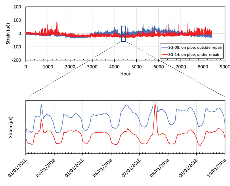
Figure 3 shows a typical comparison plot of the strains over time for paired strain gauges #14 (beneath the repair) and #8 (remote). It is the strain ranges that are of interest; this is highlighted for the week beginning Jan. 3, 2018, where it can clearly be seen that the strain range over a given day is less beneath the repair than it is remote, thus confirming that the composite repair is effective in reducing the load carried by the pipe.
This reduction in strain range can be used to re-assess the expected fatigue life of the crack-like features, and a comparison between the two analyses will quantify the benefit provided by the repair.
The strain gauge data collected during the 350-day period was fed through a rain flow cycle counting algorithm in 2 N/mm2 increments to provide a load spectrum that could be used in the fracture mechanics analysis. Maximum principal strains were converted to equivalent stresses by multiplying the Young’s modulus of the steel line. Analyses were conducted in pairs using the data from each pair of strain gauges.
First, the load spectrum from the strain gauge outside the repair was applied to the maximum crack size considered to have passed a hydrotest for an equivalent of 53 years (the time the line had been in service, prior to the repair). This enabled an estimate to be made of the maximum probable crack size at the time of installation of the composite repair.
Next, the number of years required to grow this defect to the critical depth for failure at the design pressure was calculated. This was considered to be the remaining life of the pipeline without a repair.
This second part of the assessment was re-run using the load spectrum recorded from beneath the repair to give the remaining life of the pipeline with the repair. In this way, the benefit of the composite can be expressed in terms of life extension.
The results indicated that the remaining life with the repair was expected to be 276 years versus 106 years without the repair. This was the minimum life extension predicted from each set of paired strain gauges.
The repair gives the added benefit that the crack-like features are no longer ‘surface-breaking’ but become “embedded features,” protecting them from potential environmental issues. This additional benefit was not considered in the remaining life assessment, which considered surface-breaking defects only.
The measured load data was used to determine the likely remaining safe operating life. The repair gives further confidence that the features are no longer a threat to the long-term integrity of the pipeline, provided there is no future pressure uprating. Based on the completed assessments and the installed repair, the features are now expected to remain in service along with the rest of the line for the remainder of its intended life.
The DNV project and associated research has determined that fatigue lives measured for crack-like defects in pipelines repaired using composite materials in full-scale tests align well with appropriate fracture mechanics analyses.
However, lines must be properly assessed, and repairs applied appropriately to ensure effective mitigation of the threat to pipeline safety arising from crack-like features. Appropriately designed structural monitoring can be used to collect the data necessary to assess expected lifetimes of pipelines, with and without repairs.
Finally, composite repairs for crack-like defects should be installed when the internal pressure in the pipeline is at as low a level as possible, with the benefit of the repairs (extension of the fatigue life) increasing as the installation pressure reduces.
References:
HILL, P. and SWANKIE, T., Life Extension of Pipelines with Crack-Like Defects Using Composite Repairs in Proceedings of the 2019 Rio Pipeline Conference and Exhibition, Brazilian Petroleum, Gas and Biofuels Institute, IBP, 2019
SHEETS, C. Evaluating the performance of composite systems for reinforcing non-leaking crack-like defects in transmission pipelines. In Proceedings of the 2019 Pipeline Pigging and Integrity Management Conference, Houston, USA, 2019
Authors: Troy Swankie is the senior principal specialist of the Pipelines Division at DNV. He has 35 years’ experience gained in academia (University of Bristol) and the nuclear and oil and gas industries. He holds a BEng (Hons) degree in mechanical engineering and a doctorate in materials science (mixed mode fracture mechanics).
Paul Hill leads the composite repair business for TEAM Industrial Services Inc. He gained his doctorate from the University of Cambridge, U.K., studying the long-term performance of composite materials and has been working in the pipeline industry for 30 years. He is a founder member of both ISO and ASME standards committees for composite repairs.
Editor’s note: This is an abridged version of a paper presented at the Pipeline Pigging and Integrity Management Conference, Houston, Texas, USA

Comments