August 2022, Vol. 249, No. 8
Features
Integrity Management of RNG Pipelines
By Jim Finch, CenterPoint Energy and Michael Kobelak, Intero Integrity Services
(P&GJ) — CenterPoint Energy operates more than 80,000 miles (130,000 km) of natural gas pipelines and serves over 4.7 million metered natural gas customers across six states: Indiana, Louisiana, Mississippi, Minnesota, Ohio and Texas. In 2020, CenterPoint announced its ambitious goal to achieve net-zero emissions by 2035.
This includes further implementation of renewables such as wind and solar, carbon capture opportunities in the natural gas supply chain, conservation/efficiencies and carbon reduction technologies including renewable natural gas (RNG).
RNG is a low-carbon natural gas equivalent produced from livestock waste, city sewage, organic/food waste and other sources. Producers collect this waste in anaerobic digesters where biogas forms.
Once formed, the producer then processes the gas until the chemical composition matches the acceptable specification for injection into existing natural gas infrastructure. The RNG industry continues to grow, with supply increasing almost 300% in the last five years.
Apart from the environmental benefits, RNG aids in energy diversification, rural economic sustainability and waste reduction in general.
Various industry experts have heavily researched RNG over the last 20 years. Geological and renewable natural gases are almost entirely composed of methane (CH4) as well as other trace constituents.
Refined geological natural gas typically consists of 90% to 98% CH4 and trace hydrocarbons such as propane (C3H8), ethane (C2H6), butane (C4H10), pentane (C5H12) and hexane plus (C6+).3
Trace diluents such as nitrogen (N2), carbon dioxide (CO2) and hydrogen (H2) are also commonly present.4 Managing or processing these trace constituents from geologically derived natural gas is well understood and have been tested. RNG, processed for pipeline injection, consists of 95% to 98% CH4 as well as other hydrocarbons and diluents found in geological natural gas.5 Because of the variability and composition of the fuel stock, the risk for contaminant breakthrough exists.
These breakthrough scenarios may cause undesired byproducts such as increased CO2, water (H2O) and ammonia (NH3), to name a few, resulting in increased pipeline integrity risks.
Operators typically install monitoring instrumentation inline to identify potential subpar gas compositions influenced by the variability in the biogas fuel stock. Operators can monitor hydrocarbon composition, inert gases, diluents and other parameters such as wobble number and specific gravity.6
There is propensity for biological breakthrough in both geological and RNG. Microbes and bacteria, including sulfate-reducing bacteria (SRB), acid-producing bacteria (APB) and iron-oxidizing bacteria (IOB), can cause accelerated corrosion on carbon steel.7
Commonly referred to as microbiologically influenced corrosion (MIC), these bacteria/microbes can adhere to the internal surface of the pipes and develop accelerated pitting corrosion. Some failure reports indicate MIC growth rates as high as 3/8 inch (9.5 mm) per year.8
To investigate the potential effects of the RNG tie-in on transmission line integrity, CenterPoint decided to perform a baseline integrity assessment of the pipeline near and downstream of a pending RNG tie-in.
RNG Tie-In
CenterPoint operates a natural gas transmission pipeline (NE4018) in Indiana that feeds the town of Huntington and the surrounding area. The pipeline includes sections that are 10 and 8 inches in diameter with multiple wall thicknesses and pipe grade changes.
The pipeline contains electric resistance welded (ERW) and seamless pipe with a maximum allowable operating pressure (MAOP) of 400 psig (27.6 bar). A third-party approached CenterPoint interested in constructing an interconnection point on this pipeline to inject RNG for delivery to natural gas customers.
A nearby cattle farm would provide the RNG feedstock for production, which the third party would transport through a low-pressure pipeline to the connection point, pressurize through a compressor and inject the RNG into the CenterPoint pipeline. CenterPoint would monitor the quality of the RNG using a gas chromatograph.
Both parties can stop flow if the RNG fails to meet predetermined composition criteria. The CenterPoint integrity management team began a review of this request in 2017, but it was not until 2021 that construction was scheduled to begin. The integrity management team was notified in the spring of 2021 that construction would begin in August of the same year.
After internal discussions, CenterPoint decided to perform a baseline inspection on the sections of the pipeline upstream and downstream of the connection point to determine if the introduction of RNG has a detrimental effect on the pipeline.
CenterPoint determined many common assessment methods used to achieve pipeline compliance did not meet their data requirements, such as direct current voltage gradient (DCVG) surveys or hydro-testing.
Operators use DCVG surveys to detect stray currents in surrounding soil propagated through compromised pipeline coating (e.g., cracks, disbondment, general degradation). This method effectively screens coating degradation but does not provide integrity information regarding carbon steel pipeline integrity.
Best practices involve excavating areas of detected stray current and directly assessing the pipeline and coating.
Hydro-testing, on the other hand, can indicate immediate pipeline integrity concerns. The process involves isolating the pipeline segment and pumping in water. The testing company increases and monitors the water pressure above the pipeline MAOP for several hours.
If the pressure remains constant for a prescribed duration, the pipeline passes the hydrotest. If the pipeline pressure declines beyond a threshold amount, the pipeline fails the hydrotest.
The potential option to excavate several thousand feet of pipe for direct assessment could yield adequate data, but CenterPoint determined this method not to be economically feasible and significantly burdensome to the environment.
Inline inspection (ILI), however, allowed CenterPoint to gather comprehensive integrity data suitable to monitor any potential integrity effects of RNG. The construction of this single-feed transmission pipeline did not allow for free-swimming ILI, and CenterPoint could not easily isolate the line and take it out of service for a tethered inspection or to accommodate other pipeline modifications.
Intero’s Pipe Explorer robotic ILI crawler fit the operational constraints and associated timeline. For these reasons, CenterPoint selected the Pipe Explorer for the baseline integrity assessment.
Intero’s magnetic flux leakage (MFL) inspection division (formerly Pipetel) has operated the fleet of Pipe Explorer robotic crawlers since 2011. These robots are tetherless, self-propelled, bidirectional, and can launch and receive from a single size-on-size hot tap fitting.
They provide a 50% natural gas bypass while collecting high-resolution MFL, deformation and video data in live pressure and flow conditions.
Pipe Explorer robots retain similar anatomy across the fleet and can inspect pipelines from 6 inches to 36 inches. The center of the robot carries high-resolution MFL sensors. This sensor collapses and demagnetizes to allow for the negotiation of challenging bends and mechanical features, including 90° miter bends and unbarred tees.
The noses, located on the front and rear of the robot, transmit real-time video data to the operator as well as capture deformation data with the laser deformation system (LDS).
The drive modules expand and contract to push against the pipe wall and create traction for the robot to drive upstream or downstream of the pipe. The steer modules actively roll and pitch to accommodate challenging bend groups and mechanical features.
Rechargeable batteries power the Pipe Explorer robots, which can inspect to a range of 1,500 to 2,000 feet (457 to 610 meters) prior to returning to the launch location. When inspecting from point-to-point, for example, stopple-to-stopple, the robot inspection range is up to 2,500 feet (762 meters).
The range can extend even further by setting up 2-inch fittings at predetermined locations and using inline charging (ILC) technology. The robot uses wireless technology for data transmission and self-powers, allowing it to methodically navigate almost any bend angles and mechanical features while inspecting pipelines.
Project Preparation CenterPoint decided to inspect a continuous mile (~5,000 ft [1,524 meters]) of the 8-inch pipeline with 300 feet (9 meters) of pipe upstream of the proposed RNG injection point with the Pipe Explorer 8 robot (8-inch configuration).
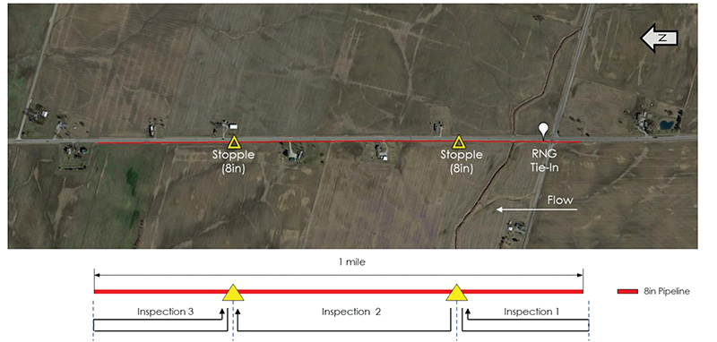
Intero recommended the use of two 8-inch stopple fittings installed 1,000 to 1,500 feet (305 to 457 meters) from the desired inspection limits (Figure 2).
The project team divided the 1-mile (1.6-km) segment into three discrete inspection segments:
- Inspection 1: South stopple to the south inspection limit and back
- Inspection 2: South stopple to the north stopple
- Inspection 3: North stopple to the north inspection limit and back
The Indiana Department of Transportation (INDOT) approved a permit to facilitate the excavations required for the stopple fittings, since the pipeline traversed the right-of-way (ROW) of a state highway.
Inspection Execution
After the installation of two stopple fittings, Intero completed the three Pipe Explorer inspections for CenterPoint from May 3 to 5, 2021.

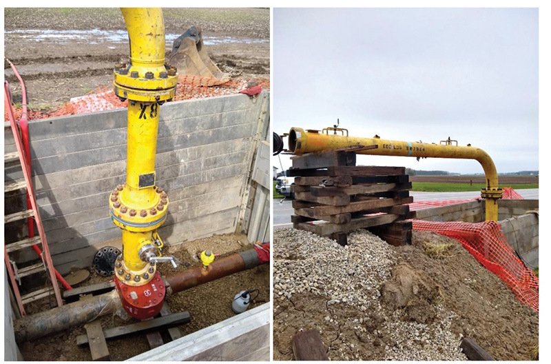
Figure 3 shows the stopple site with Intero’s temporary launch equipment: a typical setup for a pipe explorer inspection. CenterPoint welded the 8-inch stopple fitting, installed the sandwich valve and then tapped the pipeline.
Intero provided the temporary launch system composed of the following fittings installed on top of the sandwich valve:
- Sleever: A spool piece with a stainless steel insert deployable through the sandwich valve was used to provide additional traction for the robot, as well as protect the valve from foreign debris.
- Spool: Optional fitting was used to increase height and bring the launch barrel above grade.
- Elbow and launch tube: The robot is inserted and removed via the launch tube.
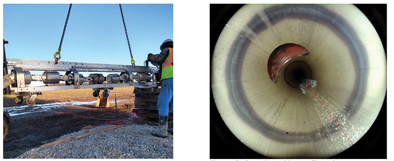
Once CenterPoint installed and pressure-tested the equipment, the lifting crew aligned the robot and tray with the launcher. A crane suspended the tray as the robot drove into the launcher (Figure 4). Once inside, CenterPoint purged and equalized the chamber to the line pressure of 390 psi (27 bar).

The robot drove through the elbow and the vertical segment before negotiating the hot tap fitting.
Once inside the pipeline, the MFL sensor deployed and magnetized to begin collecting MFL data. An Intero operator controlled the Pipe Explorer robot with real-time access to the robot systems, including data acquisition, odometry, robot health, battery and a live video stream (Figure 5).
In the case of Inspections 1 and 3, the robot collected data to the respective inspection limit based on odometer measurements. The Pipe Explorer robot then returned to the insertion location to be retrieved from the temporary launcher.
Inspection 2 required the temporary launcher to move from the south stopple location to the north.
CenterPoint performed this while the robot actively inspected the pipeline.
Review, Validation
Intero submitted the MFL and LDS data coverage reports to CenterPoint within several hours of completing the respective inspection sections. Both data sets obtained 99.9% pipeline coverage through 5,115 feet (1,559 meters) of pipe. Intero combined the inspections and provided a preliminary report on June 7, 2021. Intero reported no immediate indications on the preliminary report.
Intero submitted the final report to CenterPoint for the amalgamated inspections on July 5, 2021.
Again, Intero reported no immediate or “Year One” conditions. Intero found several minor indications and CenterPoint completed four excavations on the pipeline to validate the findings, and to perform material testing on the pipeline.
With this baseline inspection in place, CenterPoint can carry out future assessments using Pipe Explorer 8 and the existing stopple fittings, if or when the RNG connection is completed. Intero can also provide a run comparison and correlate all previous and future metal loss indications and highlight any potential RNG-induced corrosion.
Summary
The demand for sustainable natural gas with a reduced carbon footprint, as well as supply potentials for RNG, continue to grow. It is important to leverage existing pipeline networks to transport RNG safely, economically and sustainably. As an industry with limited experience of potential impact of RNG to pipeline integrity, conducting ILIs allows operators to prudently approach and monitor any potential adverse impact to pipeline integrity.
Robotic inspection methods such as the Pipe Explorer can support operators as a viable integrity management tool as the industry transitions toward more renewable gas supplies.
CenterPoint conducted a targeted baseline inspection of an 8-inch transmission pipeline prior to an RNG tie-in without isolating or disrupting gas services. Intero’s Pipe Explorer robotic crawler acquired an integrity snapshot of the pipeline through MFL, LDS and internal video data prior to the RNG tie-in. Intero inspected a mile of the single-feed transmission pipeline with two stopple fittings over the course of three days.
CenterPoint intends to repeat the inspection and compare the integrity data after several years of RNG integration. This comparison data will be invaluable to determining the long-term effects of RNG on pipeline integrity.
References:
1 CenterPoint Energy, 2022, “Net Zero by 2035 and Scope 3 Goals,” Accessed March 1, 2022, https://sustainability.centerpointenergy.com/test-2022/net-zero/.
2 CenterPoint Energy, 2021, “Renewable natural gas: basics and benefits.” RNG Fact Sheet. Accessed March 1, 2022, www.centerpointenergy.com/en-us/InYourCommunity/Documents/201230- 04_MN_RNG_FactSheet_General.pdf.
3 Wiley, K. 2018, “Renewable Natural Gas (RNG): Gas Quality Considerations,” Presentation, GTI.
4 Enbridge Gas, 2022, Learn About Natural Gas. Accessed March 1, 2022, www.enbridgegas.com
5 U.S. EPA, OAR, Climate Change Division. 2020. “An Overview of Renewable Natural Gas from Biogas.”
6 Northeast Gas Association, GTI, 2019, “Interconnect Guide for Renewable Natural Gas (RNG) in New York State,” Final Report, NY: NGA, GTI, 17.
7 Northeast Gas Association, GTI, 2019, “Interconnect Guide for Renewable Natural Gas (RNG) in New York State,” Final Report, NY: NGA, GTI, 14.
8 Gu, T. and B. Galicia, 2012, “Can Acid Producing Bacteria Be Responsible for Very Fast MIC Pitting,” Paper NACE-2012-1214, Salt Lake City: NACE Corrosion.


Comments