
May 2023, Vol. 250, No. 5
Features
An Operator’s Perspective: How to Comply with New US Gas Gathering, ILI Regulations
By Bernardo Cuervo and Mark McQueen, ENTRUST Solutions Group
(P&GJ) —Traditionally, most gas gathering lines were small-diameter, low-pressure systems traversing sparsely populated areas, posing little risk from a business, safety, and environmental perspective. More recently, the volume of gas transported through gathering systems has increased significantly due to the advancements in horizontal drilling and hydraulic fracturing techniques.
Subsequently, gas gathering systems have evolved into larger-diameter pipelines operating at much higher pressures in formerly rural areas. As a result, the Pipeline and Hazardous Materials Safety Administration (PHMSA) issued a final rule that expands Federal pipeline safety oversight to all onshore gas-gathering pipelines. This new rule changes the definition of a regulated gas-gathering pipeline.
More than 400,000 additional miles will be covered by Federal reporting requirements. This paper describes how a competent and proactive operator implemented a program to comply with the new regulations and prepared thousands of miles of gathering pipelines for inspection with ILI tools.
Introduction
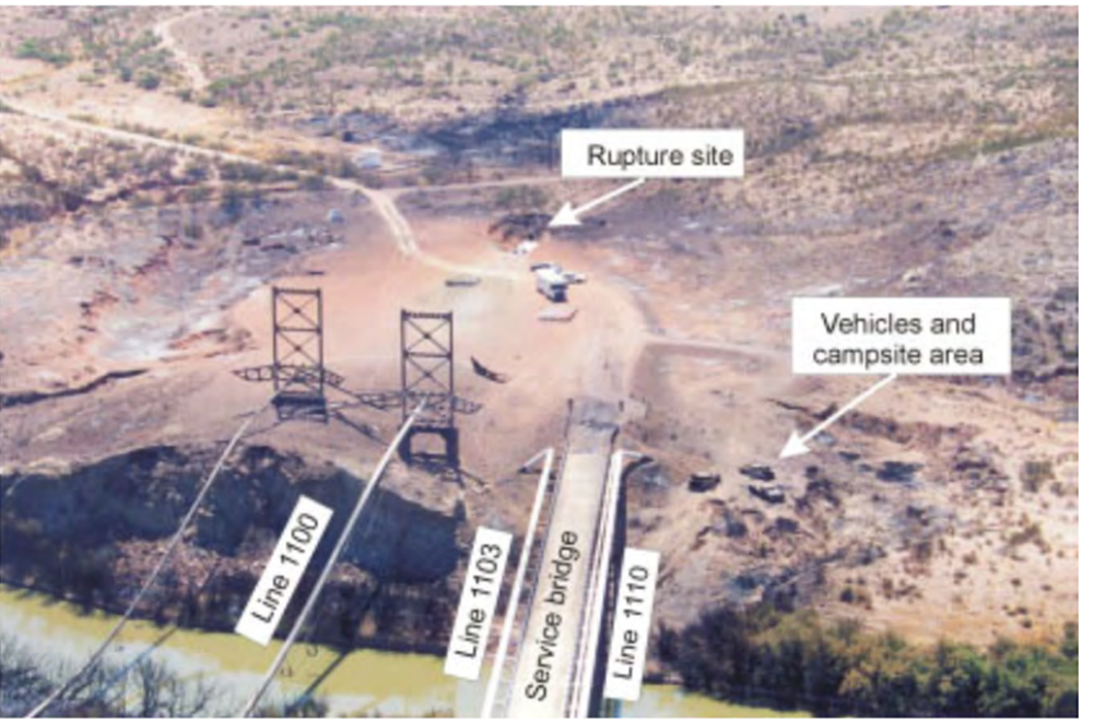
On Aug. 19, 2000, a 30-inch natural gas transmission pipeline ruptured adjacent to the Pecos River near Carlsbad, New Mexico. (Figure1) The released gas ignited and burned for 55 minutes.
Twelve persons who were camping under a concrete-decked steel bridge that supported the pipeline across the river were killed.
The National Transportation Safety Board determined that the probable cause of the natural gas pipeline rupture and subsequent fire was a significant reduction in pipe wall thickness due to severe internal corrosion. The operator’s corrosion control program failed to prevent, detect, or control internal corrosion in the pipeline [1]. The pipeline segment had never been internally inspected in a period of almost 50 years.
After the accident, the then Research and Special Programs Administration (now PHMSA) issued the Advisory Bulletin ADB-00-02, 8/29/00 to advise natural gas pipeline operators of the need to review their internal corrosion management programs and operations.
A revised inspection form was issued to include more detailed questions about internal corrosion. The revised Form-1 (192-90), Evaluation Report of Gas Transmission Pipeline included more detailed questions such as “Does the operator address fluid accumulation in unpiggable lines?”
Today, more than 20 years after the Carlsbad explosion, many gas gathering pipelines have design, operating parameters, and associated risk factors similar to larger interstate transmission lines. In the past, gathering lines had been lower-pressure, smaller-diameter lines, typically situated in lesser populated rural areas and therefore lower risk.
The potential safety and environmental consequences of a gas pipeline rupture are proportional to the pipeline's diameter and operating pressure. New drilling technologies and an increase in hydraulic fracturing (“fracking”) have dramatically increased the volume of gas that can be extracted from a single production site.
Consequently, the volume of gas transported by gathering lines has also increased significantly. For instance, the National Association of state Pipeline Safety Representatives (NAPSR), a non-profit association of state pipeline, a safety official has observed rural gathering lines as large as 30 inches in diameter with an MAOP as high as 1480 psi. [2]
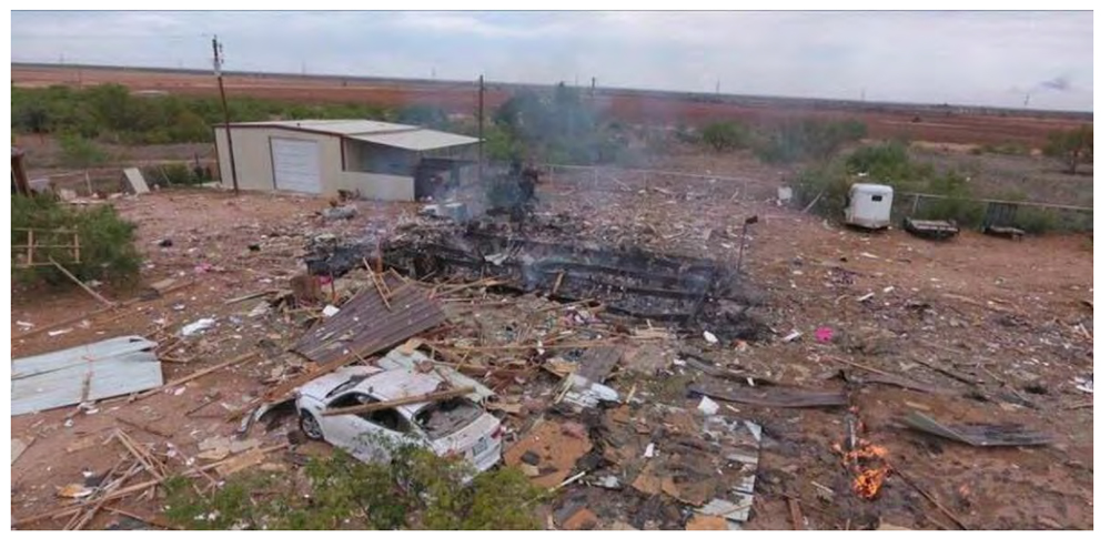
On Aug. 9, 2018, corrosion on a 10-inch gas-gathering line resulted in an explosion in Midland County, TX. (Figure 2). The explosion killed a 3-year-old girl and severely burned three other members of her family. The Railroad Commission of Texas incident report indicated that the pipeline had been leaking gas through a dime-sized hole. The gas in the 10-inch pipeline was not odorized. The pipeline was about 20 feet from the front of the family's home.
After this and other incidents, PHMSA revised the Federal Pipeline Safety Regulations to improve the safety of onshore gas gathering pipelines. The Federal Pipeline Safety Regulations (49 Code of Federal Regulations (CFR) section 192.3) defines a gas gathering pipeline as a pipeline that transports gas from a current production facility to a transmission line or main.
To determine whether an onshore gathering pipeline is a regulated onshore gathering pipeline the operator must use API RP 80, Guidelines for the Definition of Onshore Gas Gathering Lines in conjunction with 49 CFR 192.8 paragraph (b), whereby “Each operator must determine and maintain for the life of the pipeline records documenting the methodology by which it calculated the beginning and end points of each onshore gathering pipeline it operates.”
On Nov. 15, 2021, PHMSA published a final rule titled: “Pipeline Safety: Safety of Gas Gathering Pipelines: Extension of Reporting Requirements, Regulation of Large, High-Pressure Lines, and Other Related Amendments" (86 FR 63266)
How to Comply
The Final Rule revises the Federal Pipeline Safety Regulations (49 CFR Parts 190-199) to prevent and detect threats to pipeline integrity, improve public awareness of pipeline safety, and improve emergency response to pipeline incidents.
The final rule extends reporting requirements to all gas gathering operators and applies a set of minimum safety requirements to certain gas gathering pipelines with large diameters and high operating pressures. In addition, the final rule requires operators of all onshore gas gathering lines to report incidents and file annual reports under Part 191.
The purpose was to monitor the safety performance of gas gathering lines that were previously exempt from Federal reporting requirements.
The effective date of the final rule was May 16, 2022.
Regardless of their size, regulated gathering lines are required to comply with safety reporting requirements and minimum safety standards in 49 CFR parts 191 and 192. There are several categories of regulated onshore gathering lines.
They are:
Type A – Previously regulated under 71 FR 13289 since 2006.Type A Gathering lines operate at relatively higher stress levels (hoop stress of 20% or more SMYS and for non-metallic >125psig) and are located in Class 2, Class 3, or Class 4 locations. (Type A gathering pipeline in Class 1 locations are excluded as PHMSA determined that the potential consequences of a release of a smaller-diameter pipeline with a lower maximum allowable operating pressure (MAOP), in a sparsely populated area, would be minimal.)
Class 2 location is any class location unit that has more than 10 but fewer than 46 buildings intended for human occupancy. (A class location unit is an onshore area that extends 220 yards (200 meters) on either side of the center line of any continuous1- mile (1.6 kilometers) length of pipeline).
Class 3 is any class location unit that has 46 or more buildings intended for human occupancy; or an area where the pipeline lies within 100 yards (91 meters) of either a building or a small, well-defined outside area (such as a playground, recreation area, outdoor theater, or other place of public assembly) that is occupied by 20 or more persons on at least 5 days a week for 10 weeks in any 12-month period. (The days and weeks need not be consecutive.)
Class 4 location is for any class location unit where buildings with four or more stories above ground are prevalent.
These pipelines operate at relatively higher stress levels. Section 192.9(c) subjects Type A regulated gathering lines to the same requirements as gas transmission pipelines, with a few exceptions, due to the high potential consequences of an incident on a high-stress pipeline in a populated area.
Type B – Previously regulated under 71 FR 13289 since 2006. Type B gathering lines are lower-stress pipelines (hoop stress <20% SMYS and for Non-metallic <125psig) in Class 3, Class 4, and certain Class 2 locations. Title 49 of the CFR in Section 192.9(d) subjects Type B to a less comprehensive set of requirements since such pipelines operate at lower stress levels than transmission pipelines.
Examples of the requirements for Type B gathering pipelines are establishing an MAOP as well as installing and maintaining line markers according to the requirements of transmission lines.
New Type C – The new Type C gathering line classification is defined as gas gathering lines in Class 1 locations that have an outer diameter of 8.625 inches or greater and operate at an MAOP producing a hoop stress of 20% or more of SMYS, or if the pipeline is non-metallic or the stress level is unknown, operates above 125 pounds per square inch gauge.
New Type R – The new Type R gathering line is defined as any other gathering lines in Class 1 and Class 2 locations and are subjected to reporting requirements under part 191 only.
To Pig or Not to Pig
This proactive operator in preparation for the new rule began to ascertain the feasibility of ILI for thousands of miles of gathering pipelines for inspection.
Even though Type A, Type B and Type C regulated gathering lines are exempt from the requirement that new gas transmission lines be able to accommodate the passage of instrumented internal inspection devices (section 192.150(b)(8), Passage of Internal Inspection Devices) [3], in gathering systems, internal corrosion can be a much bigger threat than transmission due to the presence of water, CO2 or H2S and varying flow rates as well output changes.
Cleaning pigs keep the pipeline running efficiently, while ILI tools could provide material property and attribute data (diameter, wall thickness, seam type) on every pipe joint. In addition, ILI provides critical data regarding the condition of the pipe itself. More than 90% of the reported incidents in gas gathering lines are caused by internal corrosion. [4]
Large-diameter gathering lines are still exempt from the requirements in parts 191 and 192 if they are located in Class 1 locations despite their physical and functional similarities with transmission pipelines and their increased potential for adverse consequences in the event of an incident.
The potential safety and environmental consequences of a gas pipeline rupture are proportional to the pipeline’s diameter and operating pressure. As ILI yields the highest-per-mile discovery of anomalies, running cleaning pigs and ILI tools require that the pipeline be piggable.
That is the pipeline must have internal dimensions suitable for the pig passage, and launchers and receivers must be of the right dimensions for the length and type of device that will be inserted.
For high-risk pipelines, it would be advisable to perform a pigging feasibility study to determine a pigging plan, including the identification of necessary repairs or modifications, for a pipeline system in order that the pipeline segment can be piggable with cleaning pigs and eventually with ILI tools.
The objectives of this operators pigging feasibility study are:
- Assess the hydraulic, mechanical, and operational conditions of the pipeline to determine the feasibility to accommodate utility pigs and then ILI tools.
- Evaluate if tool velocity and pressure requirements can be met by the pipeline segment.
- Detailed operational risk-based assessment (risk for under pressurization, field operations challenges, capacity to maintain system pressures above required minimum ILI tool thresholds, and ability to generate controlled differential pressures during an eventual ILI run).
- Deliver a list of the modifications needed to enable cleaning pigs and ILI tools to pass through the line. System outages to tie in, retrofitted features, such as bends, pressure control fittings, plug valves, etc.
The elements of a pigging feasibility study are:
- Data gathering and data review – Some companies have advanced GIS and work management systems that electronically house many of the data elements such as as-builts maps, geodatabase shape files with pipeline center lines, normal operating pressures, maximum allowable operating pressures (MAOP), flow rates, pipeline questionnaires, etc. Other companies rely on paper mapping systems, inspection reports, and maintenance records as primary sources for the data.
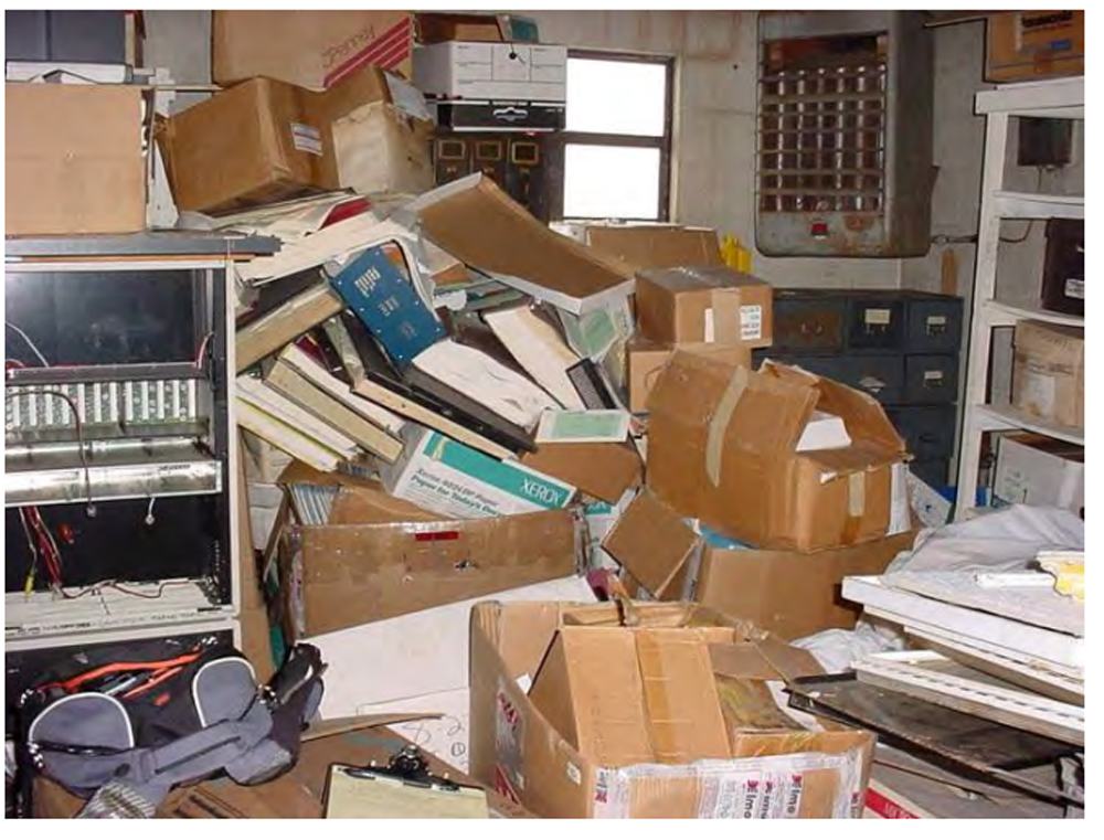
Some others are not that lucky and have all the information but need a little bit of help to find it (Figure 3). It is important to remember that all available information can be digitized, indexed, and sorted out by data specialists.
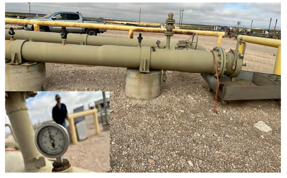
- Site Visits – A particularly important source of information are field visits and interviews of the people primarily responsible for the maintenance and operations of the pipeline. Many times, there is no replacement for first-hand field knowledge of the pipeline and its history.
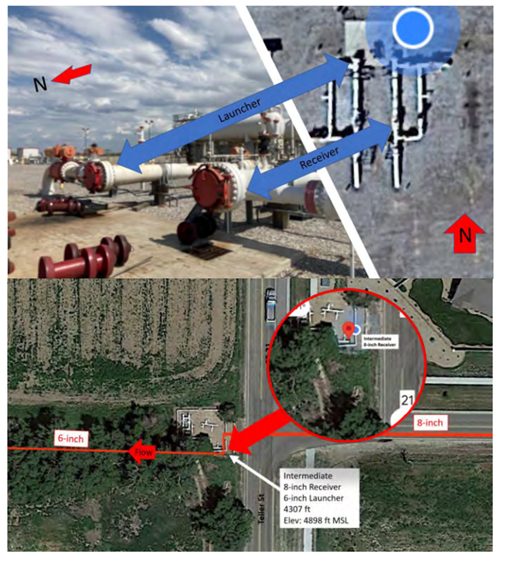
In all cases, a comparison between the geographical data and the location of taken photos is to confirm that the visited pipeline location matches up with the GIS pipeline center line depicted location. (See Figure 4).
- Operating Conditions – Evaluate historical pressure and flow data to determine if gas velocities in the pipeline can be maintained between an upper and lower threshold to accommodate off-the-shelf ILI solutions, during a specific time window, and for the estimated duration of the future ILI survey. The minimum pressure in the pipeline will need to remain above a minimum threshold specified (depending on the type of pig) for proper tool operation.
 Figure 4: Matching GIS center line and physical location in the field.
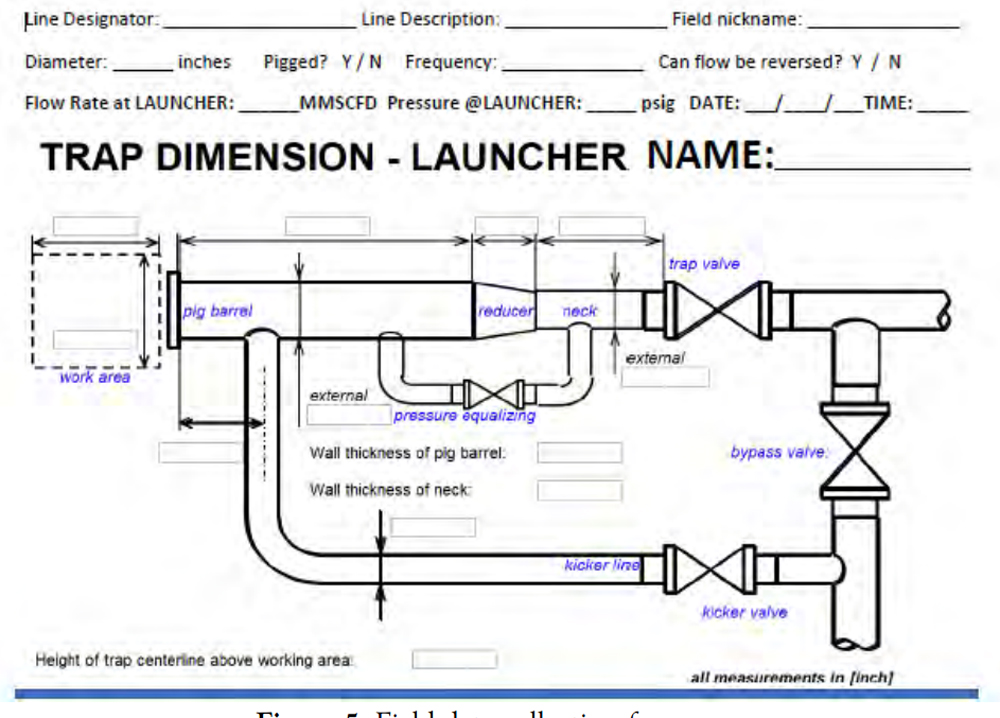
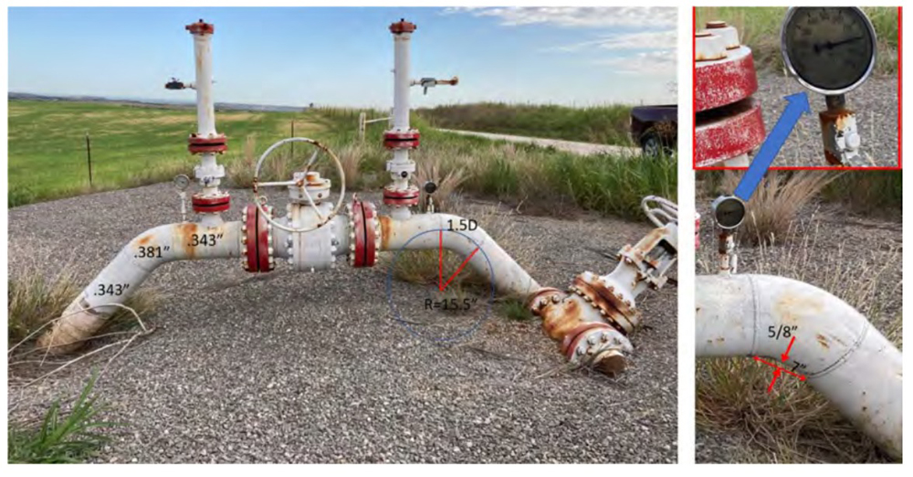
 - Mechanical Analysis – Plan development for the use of temporary (or permanent launchers and receivers) to run utility pigs (cleaning and gauge) and ILI tools. If the line has launchers and receivers, it will be necessary to verify their dimensions to ensure that the pipeline can accommodate minimum requirements for cleaning pigs and ILI tools (Figure 5).
A review of the pipeline attributes for each pipeline segment to determine the ability to inspect the pipeline with an ILI inspection tool will be required. As well as assessment of the design and operational condition of the pipeline will be necessary.
This includes the engineering review of the pipeline design, including but not limited to P&ID reviews, technical characteristics such as steel grade, type of welds, length, internal diameter (ID), elevation profile, etc. Any restrictions, bends, known ovalities, valves, and unbarred tees through which the ILI tool may need to negotiate should be identified (per NACE SP0102-2010, ILI of Pipelines).
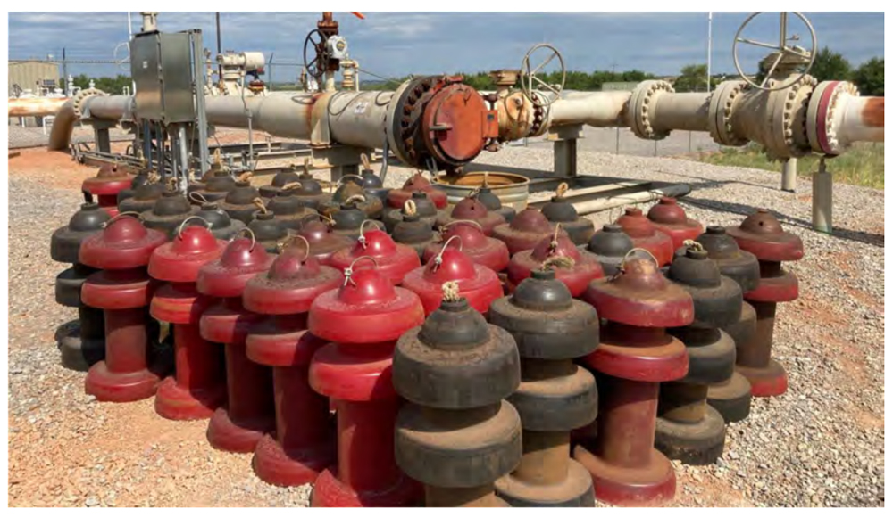
- Operational Risk Analysis – Several risks need to be evaluated. The risk to disturb regular pipeline operations during utility pigging (Figure 7) and eventual ILI operations need to be estimated. The risk assessment involves the potential for the operation to cause over or under-pressurization, the complexity of field operations, and the ability to maintain system pressures above the minimum thresholds required by standard and low-friction configuration ILI tools.
 Figure 5: A field data collection form.
Finally, the risk to have a stuck pig in the line is analyzed and compared to the capacity to increase and decrease differential pressures across the stalled pig to dislodge it.
Study Observations / Findings – To date, this operator has assessed almost a thousand miles of gathering pipeline to determine ILI feasibility at current operating conditions.
Some issues encountered include:
- Lack of system knowledge in some areas due to inexperienced/new personnel. The impact of high staff turnover rates on the pipeline industry is severe and many times its consequences are underestimated. What is more, the loss of valuable knowledge and experience is impossible to replace without a solid data collection and retention system.
- Small rural areas growing into large towns/cities. PHMSA recognizes that the state of onshore gathering pipeline safety is evolving and is in the process of collecting new information about gathering pipelines to better understand the risks they may now pose to people and the environment.
Gas gathering lines (constructed to transport shale gas), which have diameters of up to 36 inches with pressures of more than 1,000 psig are now near new urban developments.
- GIS for capturing, storing, checking, and displaying pipeline data is an invaluable tool, however sometimes the capture information does not match the actual pipeline conditions due to errors. Errors can be injected at many points in a GIS analysis, and one of the largest sources of error is the data collected.
Each time a new dataset is used in a GIS analysis, new error possibilities are also introduced. The need to have an understanding of the quality of the data is extremely important during the pipeline site visits to determine the pigging feasibility.
- Lack of corporate and regional coordination e.g., pipeline nomenclature different across systems. In many cases, an organization’s inability to share the same data across departments or divisions can lead to the formation of information silos.
Positives:
- The ILI feasibility program was driven by corporate. Top management identifies the need to comply with the spirit of the new gas gathering regulation as they recognize the need to understand the safety and risk of their system.
- The use of GIS to house many of the data elements such as as-builts maps, geodatabase shape files with pipeline center lines, normal operating pressures, maximum allowable operating pressures, flow rates, and pipeline questionnaires saves time and money.
In addition, GIS is an invaluable tool to confirm line location and features. This coupled with experienced field personnel is the perfect formula to achieve strong system knowledge.
- Many gas gathering lines are ready to be piggable and ready to be in-line inspected thanks to the effort of many proactive gas pipeline operators. This proactive approach helps them to achieve safe and efficient operations.
Next steps:
- A number of pipeline segments that are not piggable are now being considered for abandonment.
- Some other pipeline segments that are not piggable at current operating conditions are being assessed to estimate the necessary investments to make them piggable and safer.
Conclusions
- A number of incidents have occurred on high-pressure, gas gathering lines leading to fatalities, injuries, and large amounts of greenhouse gas (methane) emissions.
More than 1,000 metric tons of high-global-warming-potential methane gas are emitted, on average, with each pipeline rupture.[5] The final gas gathering rule established a new category of regulated onshore gathering lines covering higher-pressure lines that pose a heightened risk and applies existing pipeline safety requirements to tens of thousands of miles of these pipelines.
- Gathering Lines are defined in 49 CFR 192.8 as “a pipeline that transports gas from a current production facility to a transmission line or main.” Start and End Points of Gathering lines are defined in 49 CFR 192.8 as well as API RP 80 (IBR, 49 CFR 192.7)
- New rulemakings promulgated by PHMSA have caused a significant impact on operators who were not previously regulated. More than 425,000 miles of gas gathering pipelines will be regulated or subjected to annual incident reporting requirements as stated in 49 CFR Part 191.
All 2022 annual reports should include gathering line mileage. All incidents after May 16, 2023, will be required to be reported.
- The new gathering rule also provides two new designations of gathering lines: Type C and Type R. Type C - OD greater than or equal to 8.625 inches and any of the following: Metallic and the MAOP produces a hoop stress of 20% or more of SMYS or unknown stress level and MAOP is greater than 125 psig, or non-metallic and the MAOP is greater than 125 psig.
- Type R lines are all other onshore gathering lines that do not meet the existing Type A or B or new Type C definitions. Type R lines are those that are required to be reported under the new requirements but are otherwise not regulated.
- The potential safety and environmental consequences of a gas pipeline rupture are proportional to the pipeline’s diameter and operating pressure. All Type C lines that have an OD greater than 12.75 inches but less than or equal to 16 inches, or anything greater than 16 inches, must establish MAOP in accordance with 192.619 and maintain records.
In addition, Type C gathering steel lines (with some exceptions) are required to have corrosion control, and if the line has an outside diameter greater than 12.75 must establish MAOP in accordance with 192.619. You also must maintain records.
- Even though regulated gathering lines are exempt from the requirement that new gas transmission lines be able to accommodate the passage of instrumented internal inspection devices, in gathering systems, internal corrosion can be a much bigger threat than transmission due to the presence of water, CO2 or H2S and varying flow rates as well output changes.
As ILI yields the highest-per-mile discovery of anomalies, running cleaning pigs and ILI tools require that the pipeline be piggable. That is the pipeline must have internal dimensions suitable for the pig passage, and launchers and receivers must be of the right dimensions for the length and type of device that will be inserted.
For high-risk pipelines, it would be advisable to perform a pigging feasibility study to determine a pigging plan, including the identification of necessary repairs or modifications, for a pipeline system so that the pipeline segment can be piggable with cleaning pigs and eventually with ILI tools.
References:
[1] National Transportation Safety Board. Pipeline Accident Report NTSB/PAR-03/01 PB2003-916501. Natural Gas Pipeline Rupture and Fire Near Carlsbad, New Mexico Aug. 19, 2000
[2] NAPSR website at http://www.napsr.org/resolutions.html
[3] Pipeline and Hazardous Materials Safety Administration. Federal Register. Pipeline Safety:
Safety of Gas Gathering Pipelines: Extension of Reporting Requirements, Regulation of Large,
High-Pressure Lines, and Other Related Amendments. A Rule by the Pipeline and Hazardous
Materials Safety Administration on Nov.15, 2021
[4] U.S. Department of Transportation, Pipeline and Hazardous Materials Safety Administration,
Office of Pipeline Safety: Pipeline Corrosion, Baker Final Report. November 2008
[5] Pipeline and Hazardous Materials Safety Administration. New Federal Regulations Add More
Than 400,000 Miles of “Gas Gathering” Pipelines Under Federal Oversight. PHMSA 06-21. Nov. 15, 2021
Editor’s note: This paper was first presented at the 35th Pipeline Pigging & Integrity Management Conference, February 6-10, 2023. © Clarion Technical Conferences and Great Southern Press. Used with permission.

Comments