
May 2024, Vol. 251, No. 5
Tech Notes
Valve Exerciser Test Can Provide Help with Preventive Maintenance
By Nabil Abu-Khader, Training Manager, Compressor Controls Corporation
In process control, availability of all control elements is crucial to maintain smooth operation without unexpected final control elements failures. One of the most important final control elements used in today’s industry are valves.
The Valve Exerciser logic function available within Compressor Controls Corporation’s control systems helps ensure that a low-duty valve is still going to function when it is needed. It provides a way to test the operation of the valve and alert the operator if it is not functioning properly.
Valve Exerciser Concept
The Valve Exerciser function tests the operation of a valve by commanding a change in its position and then monitoring up to three process signals for changes which should result. As shown in Figure 1, if any of the monitored signal’s change, the valve has passed the test. If none of the signals indicate any change, the valve has failed the test, and an alarm is generated.
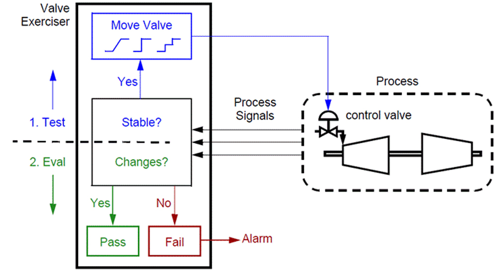
The function can monitor up to three process signals. The monitored process signals must remain stable for a period of time before a valve test is allowed. For a signal to be considered stable, any changes in that signal must have remained within an associated threshold level for a given amount of time called Confirmation Time. A time filter (Tf) constant for the signal can also be configured. The current value of a signal can be monitored using its associated signal and filter-signal variables. Each process signal has a stable variable which will be set to True when the stability criteria for that signal is met.
For Antisurge control applications, function monitors:
- Signal_1: flow (dPo1),
- Signal_2: proximity to surge (Ss), and
- Signal_3: valve position (pos)
For Antisurge Cold Recycle (SAS) control applications, the Valve Exerciser function monitors:
- Signal_1: highest proximity to surge (Ss) value from companion Antisurge controllers, and
- Signal_2: valve position (pos)
For Speed control applications, it monitors:
- Signal_1: turbine speed (N),
- Signal_2: valve position (pos)
- Signal_3: not used
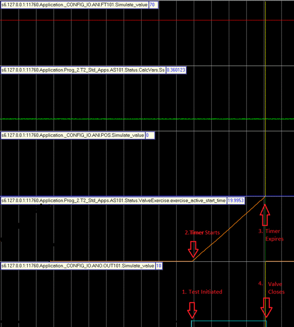
Test Operation
After enabling the test, a single one-time valve test is initiated using the Valve Exercise Run command. Periodic tests can also be configured. A valve fails the test if all of the process signals remain within their threshold levels during the entire Evaluation Time. At the end of the Evaluation Time the test is stopped, the valve position is returned to its pre-test position, and an alarm is generated.
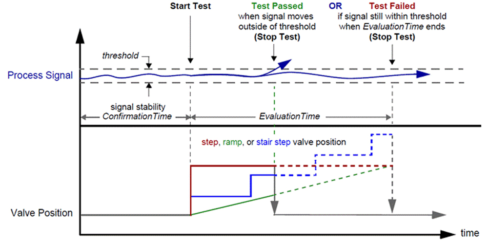
In other words, and as shown in Figure 2, a test is failed when the stable variables for all of the process signals have remained true during the entire evaluation time. Conversely, if the stable variable for any of the process signals switches to false during the evaluation time, the valve has passed the test and the test is stopped.
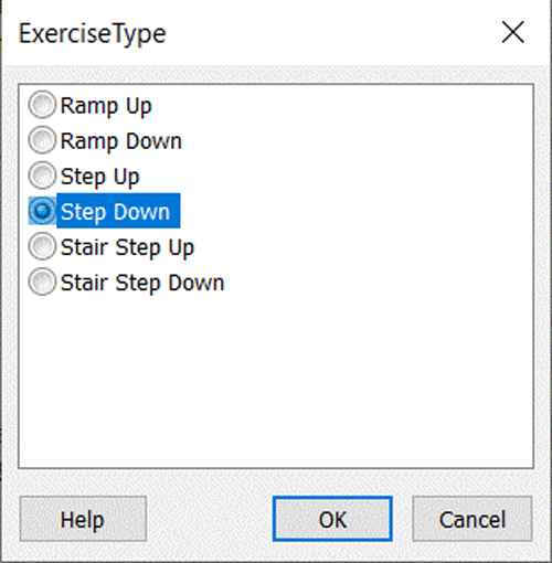
Several types of ramp and step commands can be sent to the valve as shown in Figure 3. Valve movement is applied to the position of the valve during the test. A valve test cannot be performed while the controller is in manual.
To prevent a valve test from unduly disturbing the process being controlled, a special setting (maximum output bias) allows the operator to specify a maximum allowable change in the position of the valve during the test.
Case Study
An example of a centrifugal compressor basic Antisurge control system with redundant flow transmitters (Figure 4). This process was simulated using a physical Prodigy Antisurge controller. The compressor train has its own dedicated Antisurge controller (UIC). In our case study, below were the signals to be monitored:
- Signal_1: flow (dPo1),
- Signal_2: proximity to surge (Ss), and
- Signal_3: valve position (pos)
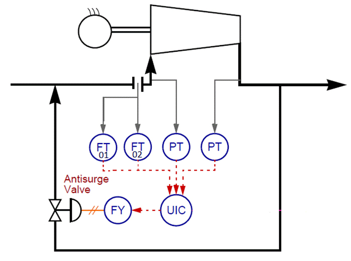
Figure 5 shows the configuration parameters for the Valve Exerciser function. A one-time step-up of 10% was selected.
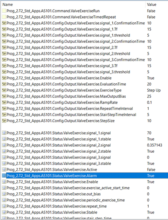
During the test, an alarm was generated because the three monitored signals (dpo1, Ss, and pos) remain stable within the evaluation time of 20 seconds. The test was initiated by operator run command. The three signals were in a stable state before the test could be initiated.
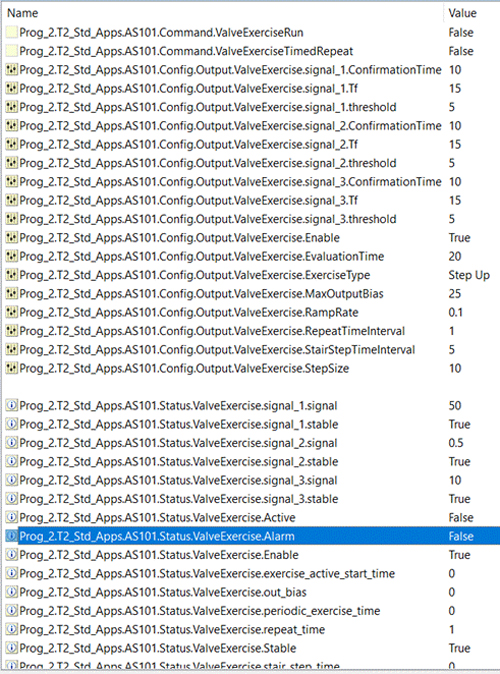
- As shown in Figure 7, no alarm was generated since one of the monitored signals (here dPo1) value changed (from 70 down to 50) during the Evaluation Time after a step-up of the valve.
Conclusion
It does not rely on the (4-20mA) position feedback signal only to monitor its valve response. Instead, its algorithm looks for process variables to detect valve movement. This guarantees the operation of the valve when needed to react as a result of a process condition.
References
- UM6451: Prodigy and Vanguard S5P Standard Logic Control Applications, CCC Library, July 2022

Comments