December 2013, Vol. 240 No. 12
Features
Predicting Power Cost of Reciprocating Compressor Manifolds

Pressure drop occurring in the cylinder gas passages, piping, vessels and coolers, as well as pulsation control devices, can cause extra power to be consumed. In a worst case scenario the additional power may overload the driver requiring a reduction in the compressor load step to reduce the flow being delivered by the compressor. This increase in power or reduction in flow come with a considerable cost or lost revenue opportunity. Therefore, accurate calculation of the pressure and power loss is required to properly size the compressor and driver.
Empirical and semi-empirical parameters required to predict pressure loss across compressor manifold elements are well established for steady flows. However, reciprocating compressor systems are characterized by unsteady oscillatory flows through the compressor manifold elements. Field experience shows that some compressor systems have pressure losses in excess of those calculated by steady flow approaches.
Therefore, the additional losses associated with unsteady flows between the compressor cylinder and the manifold, as well as the oscillating flow in the manifold, need to be accurately quantified. Determination of such losses due to unsteady flow is technically challenging.
The present research proposal aims at addressing the aforementioned deficiencies in calculating losses in compressor manifolds. The proposed research team involves industry experts and scientists with extensive experience in fluid dynamics, test measurement, pulsation analysis and modeling, and performance analysis.
There are three objectives involved in this research:
• Develop an approach to accurately quantify the power loss in the compressor pulsation control devices in oscillatory (pulsating) flows that can be used by the industry
• Provide test results of pressure-loss coefficients for various elements for pulsating flows
• Assess the implication of the pulsation power loss on cylinder performance (PV Card, Q, HP/MM)
The project will use a world-class research and development (R&D) test facility, owned by TransCanada Pipelines (TCPL). The advantage of this site is testing can be done on full scale compressor manifold components using natural gas at typical pressures experienced in compressor stations. The tests can be performed in a controlled environment and repeated as required to confirm the results. This avoids the potential errors associated with bench test sites on air or nitrogen and lower pressures.
Given the complexity with this subject, the project is estimated to take two years to complete. This article provides a summary of the team, recommended approach, schedule and costs.
Research contractors for this project are Beta Machinery Analysis (BETA), NOVA Research and Technology Corp., and TransCanada Pipelines. The advisory committee includes individuals from Kinder Morgan, ExxonMobil, Dresser-Rand, Ariel and Solar Turbines.
Mechanical Vibration Solutions
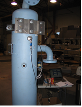
Beta Machinery Analysis has completed Phase 2 of the GMRC Project “Solutions to Mechanical Vibration Issues.” Phase 2 of the project focused on vibration control of suction bottles and scrubbers.

The research contractor for this project was BETA. Nine companies contributed financially toward this project: BETA, Cameron, Dresser-Rand, Ariel, Boardwalk, Kinder Morgan, Exterran, Compressor Systems, Inc. and Valerus. Members from these companies also participated on the project advisory committee.
Best Practices
The first phase of the project was to identify “best design practices” for scrubbers and suction bottle piping. Many common vibration problems can be avoided when these best practices are followed.
The team then identified a number of potential ideas for mitigating vibration. The list of “product” ideas was refined and eventually two ideas were selected for investigation and testing.
Vibration Absorber
The first idea involved a novel design based on vibration absorber technology. BETA created the initial design, modified it, and then built a prototype unit. Testing and evaluation took place in BETA’s test facility. The final vibration absorber design was successful and demonstrated the following advantages:
• No braces or supports required to mitigate vibration on elevated piping or scrubbers
• Applicable to fixed speed and variable speed compressors
• Very long life expectancy due to absorber design
• Interchangeable components can be stocked for immediate deployment
• Easy to install, field adjustable design
• Applicable to new projects, or can be field installed to address vibration problems
• Once the final endurance testing is complete, the design phase will be concluded.
Vibration Damper Support
An ideal vibration support would include damping elements. A properly designed damping element will suppress high-amplitude vibrations across a broad frequency band. This means a product would be effective for many different types of vibration sources.
The research product focused on a viscoelastic material as the damping component. This material does not fatigue, can withstand large deformations and is self-repairing when broken. Due the hysteretic damping behavior, it is difficult to model using conventional finite element analysis (FEA) approaches.

A European “damper-link” product was selected and tested. Braces were constructed with the damping element orientated in shear. The braces were installed and tested on a vibrating suction bottle at Dresser-Rand’s test facility located in Painted Post, NY. The damping support was also tested at BETA’s facility.
Under the right temperature conditions, the design exhibited excellent results, with very high damping. Valuable information about viscoelastic damping was developed, but the design is not yet able to be commercialized. The application technical issues may be overcome with further research.
The final report for this project will be available in 2013 to GMRC members. The project researchers presented the findings at the Gas Machinery Conference (GMC), October 2013, in Albuquerque, NM.


Comments