August 2014, Vol. 241, No. 8
Features
Protecting Our Water Keep Chemicals In The Tank

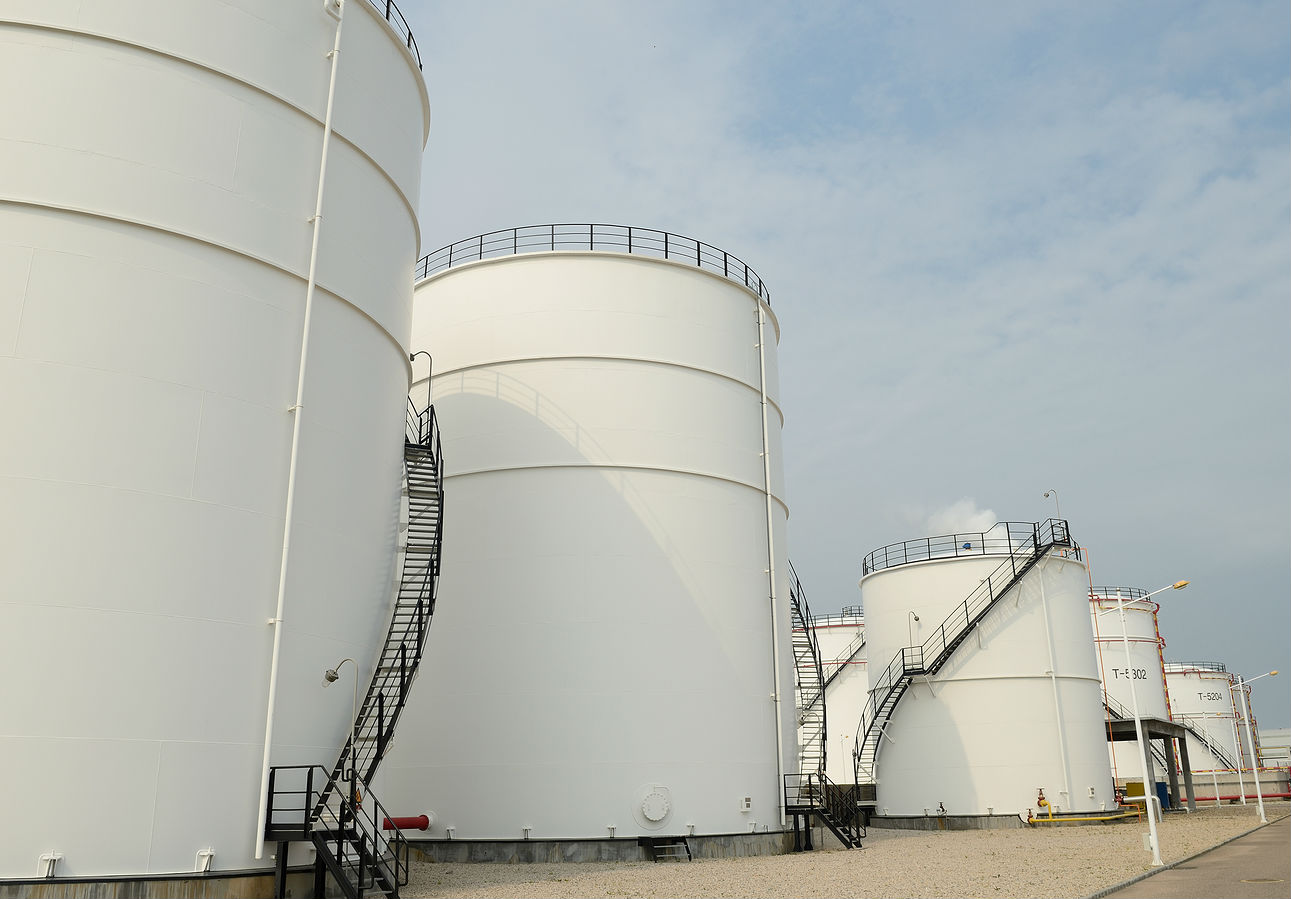
Recent events in West Virginia have shown that our water supply is in jeopardy of contamination from leaks or overfills of storage and processing tanks (Figure 1) at chemical, petroleum and water/wastewater facilities.
In Charleston, WV, a tank containing 4-methylcyclohexane methanol leaked, causing contamination of the Elk River, which left more than 300,000 people without drinking water for at least five days. The total effect of the spill may not be known for months or even years.
The company that owned the storage facility where the tank leaked – Freedom Industries – faces at least 31 lawsuits, along with state and federal investigations. As a result, the company filed for bankruptcy. In the wake of this incident, it’s clear that additional scrutiny will be coming to chemical storage facilities, along with reviews of existing regulations. But with a few precautions and a relatively minor investment, the situation could have been identified early on, and action taken to mitigate the leak and its destructive after-effects.
Instrumentation exists that will monitor the contents of a vessel and provide an alarm in the event of a leak or overfill event. These products have been used for years and are well-established and reliable.
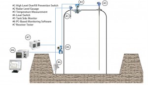
Figure 2 shows typical instrumentation for monitoring tank levels to prevent overfills and leaks. Each instrument has a specific function for keeping the contents inside the tank.

Instrument 1 – high level overfill prevention switch: The switch is installed to indicate when liquid in the tank reaches a dangerously high condition. It’s often called a high- high level switch, as it is mounted above the high level switch used to indicate the normal stop-fill point of the tank.
If the high level switch fails, the high-high level switch will prevent the tank from overfilling. High-high level switches typically include a way to function test the switch to ensure its integrity. Because a high-high level switch is mounted above the normal maximum fill point, it can be in service for years without “seeing” liquid in the tank. Because of this, the ability to test the switch on a periodic basis to verify its function is critical.
In far too many tanks, a high-high switch is the only protection against spills. This is unacceptable. Additional spill and overfill detection methods are needed.
Instrument 2 – radar level gauge: A radar level gauge continuously monitors the level in the tank. It is important that the level gauge be accurate to detect leaks, spillage or overfills. A high degree of accuracy is needed to provide an indication if the level decreases when the liquid in the tank is not actively being transferred or pumped out.
If the level starts to decrease during inactivity, it indicates a leak in the tank and the monitoring system provides an alarm. Because of these operating parameters, measurements in fractions of millimeters are taken. Radar level gauges can provide accuracy of 0.5 mm, sufficient for detecting even minor leaks.
The radar level gauge also acts as a backup to the high-high level switch.
Instrument 3 – temperature sensor: It is important to measure temperature of the liquid in the tank because the volume of most chemicals expands or contracts with changes in temperature. Without compensation, these changes in volume will look like changes in level when, in fact, the actual contents of the tank have not changed. Again, accuracy of the temperature measurement is important, in this case to provide proper compensation. Temperature sensors with multiple measurement points and accuracy of 0.1o C are required for this application.
Instrument 4 – external level switch: This level switch is mounted inside the retention dike to indicate if a liquid is accumulating. The level switch needs to detect any liquid that is present. Even rainwater accumulating after a storm should be detected because removal of this water is necessary to maintaining the appropriate volume of the dike. Essentially, any accumulation of liquid within the dike, be it water or a chemical, requires a response.
Instrument 5 – tank side monitor: This instrument performs corrected-volume calculations using the output from the temperature probe and the signal from the radar transmitter to determine the height of the material in the tank. In addition, it provides intrinsically safe loop power to the level gauge and the temperature transmitter, reads data from all connected devices and displays the values of each instrument.
Instrument 6 – PC-based monitoring software (Figure 3). This is a typical PC-based HMI software package that displays the output of each tank in a tank farm, as well as volume calculations. Such software packages are available from several suppliers. These software packages typically have web server capability built in so an operator or engineer can quickly and easily access tank information from any PC or handheld device via a browser.

The software also monitors tank level and can react to any level change. The software should have a feature that allows an inactive tank to be “locked down.” If the level in a locked-down tank drops, it would indicate a leak, and the software would produce an alarm.
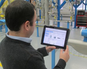
As with all alarms and events, this information can be pushed out to users via an Ethernet link so that information registers on the appropriate device, such as a PC, a tablet or a smartphone (Figure 4).

Instrument 7 – receiver tester: As described, it is critical to test high-high and external level switches to ensure proper function. Although many level switches have continuous self-checking to monitor their health, the receiver tester allows an operator to test the switch manually with a push button.
The tester can detect a short circuit, an interruption in the signal line to the measuring sensor, vibrator corrosion in the sensor or a defect in the input circuit. As a backup to the main automation system, the tester also includes relays, providing an output to an alarm or a control function, such as a diversion valve, to prevent overfilling.
Conclusion
With an instrumentation and monitoring system, spills and leaks are detected at multiple levels – with tank monitors, HMI software and receiver testers providing redundancy.
The events in Charleston make it clear that chemical storage tanks need to be secure, and that spills and leaks must be prevented whenever possible. This should extend to all industries storing chemicals that could contaminate water supplies.
In the petroleum industry, the American Petroleum Institute (API) has recommended practices for preventing and responding to spills (API 2350 recommended practices for aboveground storage tanks). In the chemical industry, most facilities that manufacture chemicals are required to have a Spill Prevention Control and Countermeasure (SPCC) plan in place.
Unfortunately, because the West Virginia facility only stored chemicals and did not manufacture them, it wasn’t required to have the site inspections and permits that a manufacturing facility would require. Lack of these requirements and the failure of the owners to provide proper level monitoring led to the incident, which was serious enough to bankrupt the company.
Proper instrumentation for monitoring storage vessels can prevent spills and identify leaks. Where these incidents cannot always be prevented, it is critical they are quickly identified, and that a response plan is in place to mitigate damage and environmental harm. Outfitting tanks with overfill prevention switches and tank monitoring instruments will provide the security needed to prevent catastrophes.


Comments