
December 2018, Vol. 245, No. 12
Features
Assuring Integrity of Polyethylene Gas Pipeline Systems
By Chris O’Connor and Richard Beedell, DNV GL, Oil & Gas
Polyethylene (PE) revolutionized low-pressure gas distribution pipeline design on a global basis. Its unique benefits make it a material of choice. To maximize benefits, gas transporters continue to push the PE design envelope with more demanding applications, larger pipe diameters and higher operating pressures.
Rapid crack propagation (RCP) is sometimes referred to as a “fast brittle fracture” or as a “linear split” by the construction industry. RCP is caused by the forced introduction of a brittle crack into a material, where a combination of material quality, temperature and internal pressure determine how far the crack will propagate along the pipe, the point at which the crack tip is blunted, and the fracture event arrested.
A critical temperature and critical pressure must be established for the conceptual conditions of RCP to take place. There must also be a fracture initiation point to enable the RCP event to commence. Therefore, the increased risk of RCP and the key variables that affect RCP performance must be considered when increasing the diameter and wall thickness of PE pipe.
Dependent Factors
RCP of PE pipes is initiated at defects within the pipeline by sudden mechanical shock, such as a high velocity impact from excavation equipment or a pipeline pressure pulse. Once initiated, ruptures can travel at high speed (100 - 300ms-1) along the length of the pipe over significant distances.
It is generally of concern in piping systems that are used to convey compressed gases because their rapid energy dissipation provides the energy to sustain crack growth. At a critical speed, the crack will become unstable, branching in a sinusoidal pattern, until it slows and stops. Alternatively, a crack may be arrested at a point where a change in the cross section occurs or a flange connection breaks the continuity.
RCP is dependent on several factors:
- Pipe diameter – as diameter increases, RCP risk increases
- Operating pressure – as stress in the pipe wall increases, RCP risk increases
- Operating temperature – as temperature decreases, RCP risk increases
- Material properties – fracture toughness, impact strength, fatigue resistance
- Pipe processing history – residual stress
Impact of Failure
Several instances of RCP have occurred in the U.S. and continental Europe, but gas companies are reluctant to share information on these and details are scarce. The potential for uncontrolled large-scale release of gas could be disastrous, and hence demonstrates the criticality and importance of assessing the performance and characteristics of this material.
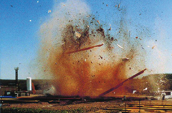
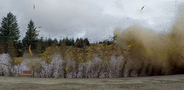
RCP of PE pipes can have varying responses depending on material properties and pipe geometry. Simulated RCP failure of buried PE pipe shows that the failure event can be explosive, generating significant pressure waves (Images 1 and 2). Fragmentation can travel at high velocity over distances of 50 meters.
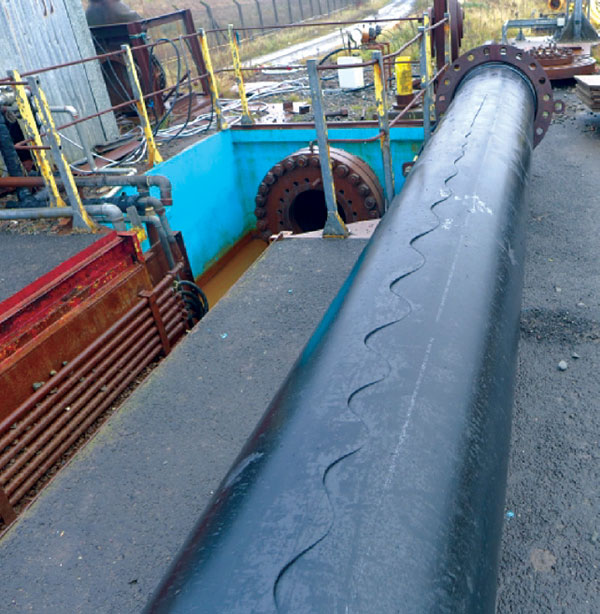
Typical features of an RCP crack are a sinusoidal crack path along the pipe (Image 3), while bifurcation of the crack into two directions may also occur. RCP can also propagate through butt fusion joints whereas research suggests cracks are arrested by electrofusion couplers.
Research
Intensive research into the mechanism of RCP in high-pressure steel transmission pipes has resulted in. This can be applied to PE networks.

In the early 1970s, the threat of RCP restricted the use of pipe greater than 315 mm diameter. To solve this problem British Gas, developed a test methodology to calculate critical pressures below which any initiated fracture would not propagate within a known pipe diameter making it possible to identify safe operating pressures.
British Gas research gave rise to the full-scale PE RCP test facility and a methodology. that became the ISO 13478 standard for RCP pipe testing. This test is the ultimate reference for assessing RCP performance.
The original test facility is now part of DNV GL’s Spadeadam Testing and Research facility Cumbria, U.K. The site provides continuance analysis of RCP and verification and certification for global manufacturers of PE material and pipe and PE pipeline operators.
Testing
RCP testing at Spadeadam is conducted in a concrete trench equipped with a cooling unit to condition the test sample at any temperature from ambient down to -15° C and a large steel pressure vessel to simulate a pressurized gas network (Image 4).

The test involves the initiation of a crack in a 24-meter length of PE pipe. The test pipe is first fused, stringed and clamped in a trench with one end connected to the gas reservoir. The pipe is then buried in gravel, cooled to a reference temperature of 0° C (Image 5).
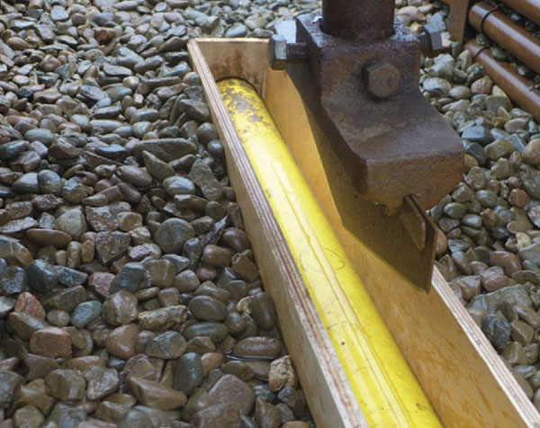
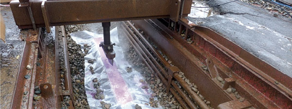
Following pressurization, a blade driven by a fast-acting pneumatic piston is used to initiate the crack in an area of the pipe (Images 6 and 7). The make-up pipe, in which the initiation is performed, can be extruded with a less resistant resin to ensure this initiation. To assure initiation of a brittle crack, a groove is also machined in the initiation zone which is cooled under the glass transition temperature of PE using methylated spirits and solid carbon dioxide mixture prior to testing.
Repeating the experiment at different levels of pressure determines at a given temperature, the characteristic critical pressure beyond which the crack propagates over more than 90% of the tested pipe length.
PE materials used for the construction of natural gas networks are of the third-generation type with highly elevated mechanical characteristics. For example, the European draft standard for PE gas networks provides a maximum operation pressure up to 10 bar for such materials. Since the risk of RCP becomes more critical at growing pressures, the importance increases to control this phenomenon thoroughly.
Hence, gas industry standards for PE gas pipelines, i.e., ISO 4437, EN1555, and GISPL2, now include an RCP requirement.
The current pass criteria for RCP taken from ISO 4437 is:
Pc > 1.5 x MOP
Where:
Pc = critical pressure, psig
MOP = maximum operating pressure, psig
MOP is determined from the standard formula knowing the pipe standard dimension ration (SDR), the MRS (minimum required strength) and C (design coefficient). Once the gas company has determined its MOP, the RCP requirement is the critical pressure of the pipe must be (at least) 1.5 times the MOP. This 1.5 factor is due to the pre-commissioning leak test pressure, which is generally done at 1.5 times the MOP. Many RCP failures occur during the leak test, because this is when the pipe sees the highest internal pressure and is most susceptible to RCP.
To determine comprehensive and accurate operating pressures to permit the usage of larger diameter PE pipes at higher pressures for a range of pipe sizes and SDR’s over the full temperature range, a series of full-scale RCP tests are implemented. These series of tests have made it possible to calculate the safe operating pressure for each pipe diameter and wall thickness over a range of operating temperatures from -20o C to +20o C. This research makes it possible to design pipeline operating pressures such that the risk of RCP occurring is minimized within the PE distribution network in the U.K.
To date, RCP has not been observed as a failure mode in the U.K. This is testament to the engineers that have worked to understand this failure method, creating appropriate operating codes that prevent the pipes being operated in conditions where they would be susceptible to RCP.
Summary
RCP is not the result of inferior PE or pipe quality, rather a combination of intrinsic material characteristics, the type of impact or damage, the pipe size and SDR, temperature and the presence of pressure in the pipe.
It is, therefore, critical for the operator of PE gas pipe distribution systems to determine whether pipe materials used within their systems have been fully tested to determine the RCP critical pressure level.
With robust verification and certification testing in place RCP of PE pipelines can be eliminated giving the necessary assurance in the integrity and safety of the pipeline asset in the event of third-party damage or poor installation. P&GJ
Authors:
Chris O’Connor is principal consultant for U.K. and West Africa with DNV GL, Oil & Gas. He is a polymer scientist and chartered engineer with extensive experience providing technology qualification and materials advisory services to the oil and gas sector.
Richard Beedell is a project engineer working at DNV GL’s Spadeadam Testing and Research Centre. His work on PE pipes and fittings includes the type approval testing of these products to ensure compliance with the Gas Industry Standards and the EN 1555 standard. He holds a MEng in Chemical Engineering.

Comments