
September 2018, Vol. 245, No. 9
Features
Natural Gas Flow Calibration Perspective
By Terry Grimley, Manager, Flow Measurement Section, Southwest Research Institute
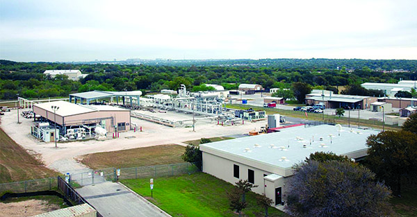
When the concept of a natural Metering Research Facility (Figure 1) was originally conceived roughly 30 years ago by the Operating Section of the American Gas Association (AGA), one of the primary goals of the facility was to improve the accuracy of flow measurement using orifice meters (and to some extent, turbine meters). By the time the facility was actually constructed and commissioned at Southwest Research Institute, the introduction of multipath ultrasonic meters for custody transfer had begun; and within the first five years of operation of the facility, Coriolis meters for gas flow were being introduced to the natural gas industry.
It may not be immediately apparent, but these three metering technologies (orifice, ultrasonic, and Coriolis) have been intertwined for the past 25 years. The advantages created by progress in one technology have been applied to the other technologies as the new technologies have continued to evolve.
It is recognized that orifice meters are intended to be built to a standard that governs the mechanical specifications for the orifice fitting, the plate, the pressure and temperature measurement locations, upstream piping configurations, etc. If an orifice meter is built and installed per the specifications described in American Petroleum Institute Manual of Petroleum Measurement Standards Chapter 14.3 (a.k.a., API 14.3), the uncertainty specification for the flow measurement can be determined from the information in the standard.
One of the topics for orifice meter research in the 1990s was to determine the piping requirements needed so that upstream piping elements, such as various combinations of elbows, valves, and other fittings, did not push the overall flow measurement result outside the uncertainty limits. This research was successful in establishing the required upstream piping lengths for publication in the standards. The research also led to the development of a new class of flow conditioners and the acceptance of the use of flow conditioners to greatly reduce the effects of flow disturbances within shorter piping lengths.
While this research improved the application of orifice meters by reducing installation effects, the overall measurement uncertainty remained largely driven by the uncertainty in the experimentally derived orifice discharge coefficient correlations included in the standards.
The uncertainty in the discharge coefficient correlations comes from a variety of sources, including the use of multiple laboratories (using different flow references), differences in meter tubes, different working fluids, etc. Additional research has shown that there is variability in the results from orifice flow measurement with a single meter tube that is related to variations in orifice meter plates, even when the plates are constructed based on the reference standards.

Improvements in measurements with an orifice meter can be made by flow calibrating the combination of the orifice plate and fitting at the operating condition of interest. This is not necessarily practical with dual chamber fittings where plates are changed to accommodate seasonal or other shifts in the flow rate. However, flow calibration is practical and cost effective for orifice flange unions with a fixed-size orifice plate (typically used for fuel gas applications.) Improvements in the uncertainty of 0.2% to 0.3% are possible and some companies are performing flow calibration of their orifice meters as a standard practice. Figure 2 shows that meters built to the API 14.3 specification may still result in errors beyond the uncertainty range stated in the standard, and that the meter accuracy can be improved by characterizing and eliminating any bias error.
Regular flow calibration of orifice meters would not likely be possible, or even considered, if it had not been for the introduction of multipath ultrasonic flow meters. Flow calibrated multipath ultrasonic meters have provided an improved target for the uncertainty level in metering stations and have necessitated the development of low-uncertainty flow calibration facilities to provide those calibrations.
However, when multipath ultrasonic meters were first introduced to the natural gas industry, the initial approach was to follow the example of the orifice meters and to design and build the meters such that they did not need to be flow calibrated. The elements of the meters that affected the accuracy of the flow measurement were to be controlled in the manufacturing process. Meter bodies could be measured to determine the acoustic path lengths, angles, and the meter bore diameter. Ultrasonic transducers could be physically measured and electronically characterized or built such that they were practically identical. Since the industry was comfortable with building meter assemblies to a specification, they were receptive to the idea that multipath ultrasonic meters would not need to be flow calibrated to meet the manufacturer-specified uncertainty of approximately 1%. The other consideration was that at the time the meters were being introduced, there were very few places in the world where ultrasonic flow meters could be tested; and in many cases, the flow testing could not reach the full capacity of the meter.
Although testing performed in the mid-1990s suggested that ultrasonic meter accuracy would benefit from flow calibration, the initial release of AGA Report Number 9 in 1998 did not include a requirement for flow calibration. In addition, ultrasonic meters were expected to have linear characteristics based on various combinations of path locations and/or internal corrections for changes in velocity profile resulting from changes in the bulk velocity. Because of the assumption of meter linearity, early meters typically only included a single meter factor that would apply to the entire flow range of the meter and provide a uniform shift in the error curve.
As ultrasonic meters started to gain acceptance, industry and the manufacturers continued to investigate the meters’ behavior over a wide range of piping installations and operating conditions. Even though it was not required by the standard, many companies performed flow calibrations and found examples of meters that exhibited non-linear characteristics that could not be corrected with a single meter factor and other meters that had errors that were larger than acceptable to the end-users Results such as those shown in Figure 3 led to the introduction of multipoint linearization for ultrasonic meters. Research also determined that, while the meters could accommodate some level of upstream flow disturbance from piping elements, the magnitude of the errors created by those disturbances were not always acceptable.
The combination of the sensitivity of ultrasonic flow meters to flow distortions and the variability of calibration results led to two practices: the standard use of flow conditioners and flow calibration. The application of flow conditioners, which were originally developed for orifice applications, significantly improved the ability of multipath ultrasonic meters to produce low uncertainty results. Once additional natural gas flow calibration facilities became available in North America with capacities sufficient to calibrate large meters, flow calibration was easier for the industry to accept and became part of the requirements in the second release of AGA Report No. 9 in 2007.
The evolution of the acceptance of Coriolis meters for gas applications has some similarity to multipath ultrasonic meters.
Prior to any level of industry acceptance, Coriolis meter testing sponsored by the former Gas Research Institute (GRI) was conducted to help establish the performance characteristics of Coriolis meters when operating on natural gas. Because Coriolis meters are flow calibrated on water as part of the manufacturing process, the testing helped to establish the applicability of the water calibration to gas applications and the degree to which the upstream piping configuration could influence the meter output. The testing involved multiple meter brands, sizes, and piping configurations and helped to support the development of the AGA technical note on Coriolis Flow Measurement that was published in 2001.
Manufacturers have continued with the development of larger Coriolis meters and research and testing to establish the transferability of water calibrations to gas applications. Even with stated uncertainty values in the range of ±0.25% to ±0.35%, improvements in the accuracy of Coriolis meters can be made through gas calibrations at the operating conditions. Since elevated static pressure stiffens the vibrating flow tube, pressure can influence the meter accuracy by producing a shift in the meter performance. While manufacturers characterize pressure effects for their meters, the uncertainty associated with those characterizations can increase the overall uncertainty of the meter when operated with gas at elevated pressures. Therefore, flow calibration at operating pressure conditions can reduce the overall meter uncertainty.
By reviewing Coriolis meter calibration results, companies that were familiar with multipoint linearization through their exposure to ultrasonic meters were able to convince some manufacturers to include the multipoint calibration capability for Coriolis meters within the meter electronics. The application of multipoint linearization to a Coriolis meter is significant because it is recognition not only of improvements that can be made by a flow calibration under the operating conditions, but also allows the correction of, admittedly small, non-linear characteristics that can appear during a flow calibration.
Over the past 25 plus years of operation, the Metering Research Facility has observed some interesting shifts in the attitude of the gas industry toward flow meter calibration. The improved availability of flow calibration services has contributed greatly to the recognition by the industry of the value of flow calibrations for all meter types. The benefits for flow calibration, regardless of technology, generally consist of reduced measurement uncertainty and increased confidence in the proper operation of the measurement system. Flow calibration has become widely accepted as a “best practice” for nearly all flow measurement applications; few would consider installing a flow meter without the assured performance that a flow calibration provides. P&GJ

Author: Terry Grimley is a Mechanical Engineer who serves as the Manager of the Flow Measurement Section at Southwest Research Institute where he is responsible for a variety measurement related projects including the operation of the Metering Research Facility. He has direct experience with a range of flow measurement technologies and is actively involved with the AGA Transmission Measurement Committee, and other industry groups.

Comments