June 2019, Vol. 246, No. 6
Features
Transmitter Signal Propagation Issues on Steel Mandrel Pigs
Over the years as a pig tracker, I have noticed that getting a good transmitter signal from a steel mandrel (cleaner type) pig has become increasingly difficult compared to smart pigs.
The last few years, with the introduction of the L-22 receiver, which provides a visual image of each pig pass, I have been able to gather evidence that provides a better understanding of what causes this phenomenon.
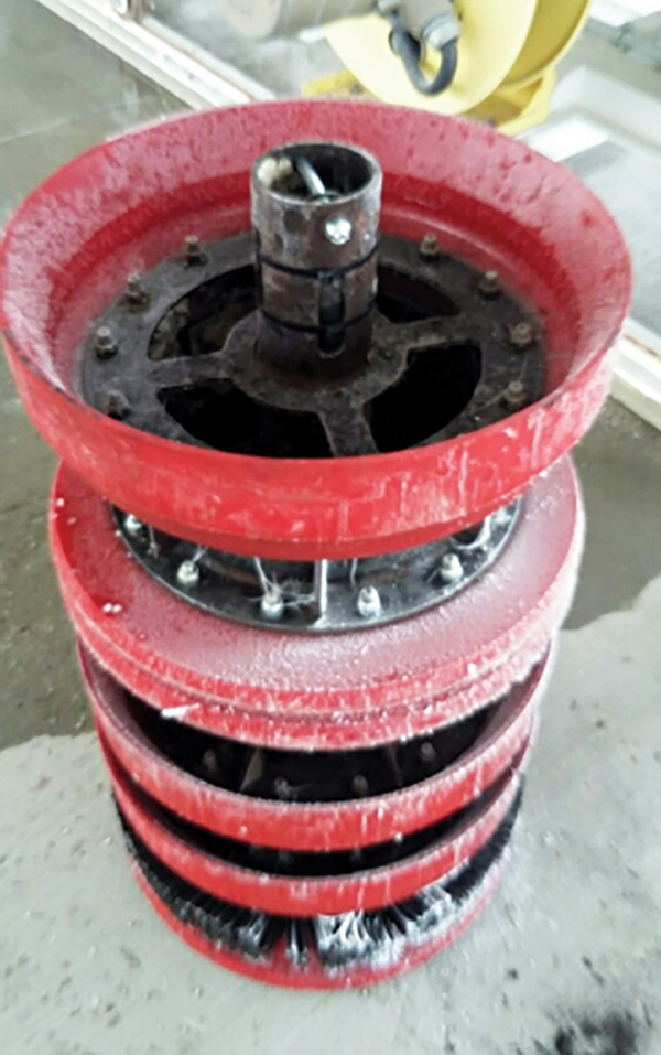
Two factors appear to be responsible for the poor transmitter signal from steel mandrel pigs: 1.) the steel in the pig surrounding the transmitter and 2.) the transmitter mounting materials and methods.
Photos of various pigs and images from pig passes recorded by the L-22 receiver help to shed some light, and I will do my best to describe the important features of each and clarify the issue of ferrous metal around the transmitter. (“Ferrous metal” is not an ideal description, because stainless steel contains iron but is non-magnetic.)
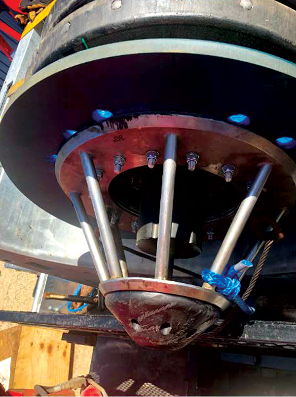
The transmitter in Photo 1 is the black object protruding from the front of the pig with the stainless steel cage. The body of the tool is stainless steel with polyurethane cups and discs. Note that the front half of the transmitter is fully exposed, and the remainder is free of any magnetic metal surroundings.
All of this allows for good signal propagation so enough of the signal strength gets through the pipe, earth, and air to the receiver, which sits on the ground above it as it goes by in the pipeline. This results in a quality signal at the receiver, Figures 5, 6, or 7.
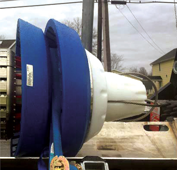
The transmitter on the caliper pig in Photo 2 is housed in the white nose area, again allowing a quality signal to get to the surface for recognition by the pig tracker. This would give a better signal due to the entire transmitter being surrounded only by nylon or aluminum (aluminum can cause eddy currents). This is an ideal example of “transmitter mounting protocol.” This tool is always easy to track.
Steel mandrel and steel tube around the transmitter results in the signal in Image 1 below. If you could see this in person, you would see that the ends of the transmitter are capped with steel, the transmitter is enclosed in a steel tube with only small slots cut in the sides, and that over half of the transmitter is within the steel mandrel of the pig. The result is that most of the signal has to penetrate two additional layers of steel pipe in addition to the pipeline steel itself in order to get out to the receiver to notify the pig tracker.
Image 1 is a 24-inch steel mandrel and steel attachment bracket cleaner pig.
In all the following images, the green line is the radio signal and the blue line is the magnetic anomaly signal. With regard to the radio signal, Images 5 and 6 are ideal pulse and continuous signals, respectively. Note that unlike Image 1, the signal is full scale vertically (indicating strength) and easily discernable from the background noise/interference preceding the pig pass.
The radio signal in Image 1 is weak and would be missed altogether by most receivers. Even with the L-22 receiver this is not what I would call a “confirmed pass” radio signal. Rather, the magnetic anomaly combined with the geophone sound is how I confirmed this pass.
Note that with any steel mandrel cleaner pig that is 20 inches in diameter or greater. The pig will leave a magnetic anomaly signal, but any smaller diameter pig will require supplemental magnets to have this benefit. MFL tools leave an “off the chart” signal that by itself can be used to track or locate the pig. Few receivers even detect the magnetic signal.
The radio signal (green) from a 24-inch steel mandrel and steel attachment bracket cleaner pig is weak is weak and would be missed altogether by most receivers.
The transmitter bracket on the 34-inch pig in Image 2 is similar to the 24-inch pig.
The radio signal in Image 3 is detectable by the L-22, but with other receivers it would maybe give 1 or 2 beeps – not enough to have a clear confirmation. This pass was confirmed by magnetic signal and geophone primarily, with the radio signal giving some additional confidence.
Image 4 show results from a 16-inch cleaner pig with magnets with a partially exposed and steel enclosed transmitter at a shallow location. Pig detection from the radio signal would have been weaker in a deeper location.
This shows an ideal magnetic anomaly signal with the magnetic field rising north, abruptly going south and receding to neutral. When magnets are installed on a pig, the technician must be careful to ensure that the magnets are all oriented with N pole in one direction and S pole of each of the magnets in the opposite direction. This ensures the strongest and clearest magnetic signal.
Image 5 is a 20-inch slow moving gel train pig with exposed pulse transmitter. This is an example of an ideal pulse transmitter pass.
Image 6 is a 10-inch polyurethane cleaning pig with fully exposed constant transmitter.
is what an ideal radio signal looks like with a buildup of signal strength, a clear null, and a receding signal. Note that at 10 inches in diameter, there is no magnetic detection.
Again, in Image 7 is a 20-inch caliper pig with continuous transmitter. Again, in Image 7 is a 20-inch caliper pig with continuous transmitter. Again, a transmitter out in the open (no magnetic material in the pig around the transmitter) yields an easy to confirm pig pass at the receiver.
Another piece of evidence in the puzzle can be seen at valves and cased road crossings. If the receiver is set just upstream of a main line valve or road casing, the transmitter signal will rise, but abruptly drop off as the pig enters either the valve or the cased pipe. In either case the pig is traveling into a greater thickness of steel and the signal is blocked.
- Stainless steel or nylon attachment brackets rather than mild steel
- Transmitter mounted in a more exposed manner
- Transmitter bracket less encompassing
- Transmitter bracket only contacting the transmitter at the middle where the null occurs
With this additional information, pipeline integrity departments can weigh the costs and benefits to determine the best way forward for their particular operations. P&GJ


Comments