September 2020, Vol. 247, No. 9
Features
When Pipelines Strain Assessment Exceeds Capacity
By J. Dawson, I. Yablonskikh and M. El Seify, Baker Hughes
The as-laid position of pipelines is not always constant, and movement can occur for several reasons, including settlement, wash-out and flooding, subsidence, landslides, earthquakes and human activity adjacent to the line.
Pipeline movement or deformation redistributes the axial force along the pipe, increasing axial tension in some locations and compression in others.
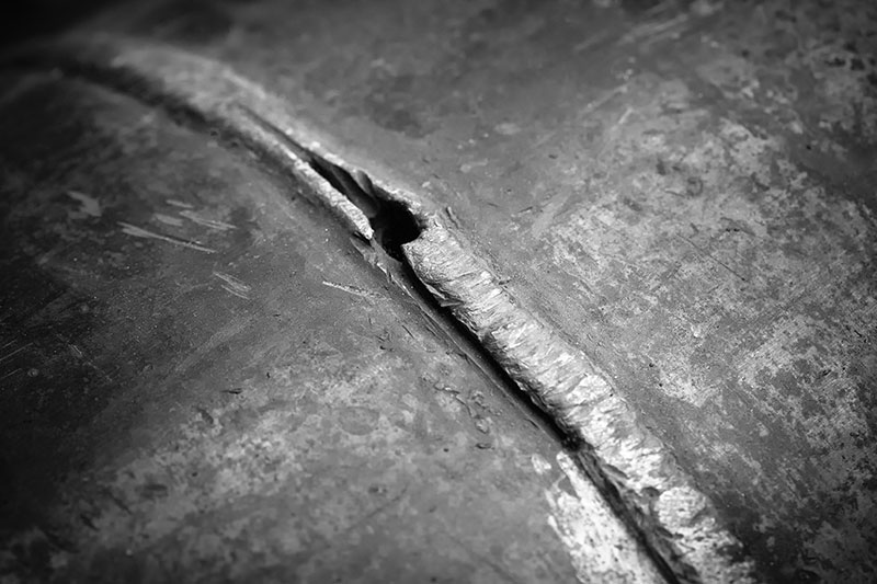
It can also give rise to pipeline curvature, which induces tensile-bending strain in half of the pipe cross section and compressive bending strain in the other half. The tensile strain can lead to pipeline leak or rupture, particularly at girth welds, and compressive strains can lead to wrinkle and buckle formation.
While the measurement of the bending component of the longitudinal strain is well understood and can be derived from routine inertial measurement unit (IMU) inline inspections, the pure axial part of the longitudinal strain has been a recognized gap in the knowledge of the strain condition of a pipeline.
Now, the inline axial strain inspection tool (AXISS) can be used to measure the pure axial strain component. The measured axial strain can originate from many sources, such as geotechnical hazards (land movement in the direction of the pipeline axis), thermal (due to temperature increase vs installation), as well as from the combination of soil restraint conditions and internal pressure effects.
Both IMU and AXISS technologies provide information regarding the presence of strain due to geotechnical events, but neither can independently provide the full total strain information.
Indeed, the technologies complement each other and the real benefit comes from using both technologies (in the same inspection) i) to identify geohazard threats acting in both transverse and longitudinal directions respective to the pipeline, and ii) to determine the total longitudinal strain demand along the entire pipeline, including at particularly susceptible locations such as girth welds, geometric anomalies and other pipeline defects.
Strain demand is the magnitude of strain acting on the pipeline and comprises both the bending and pure axial components.
The strain demand information is a required input into an engineering criticality assessment of a pipeline section that is subject to a tensile or compressive strain (from an external load).
The other input needed is the strain capacity of the pipe in question. Strain capacity is a measure of the pipeline’s capability to resist failure. In strain-based design and assessment, failure is associated with tensile fracture (ultimate limit state) or compressive local buckling (serviceability limit state).
The strain capacity will vary along the length of a pipeline as it is influenced by material properties, pipe and weld geometry and the presence of cracks or other defects. Tensile strain capacities as low as 0.2% and as high as 2% to 4% have been obtained from experimental tests.
The tensile strain capacity of pipe body material is expected to be relatively high, but at girth welds (even welds compliant with API 1104) it can be low. To obtain realistic strain limits, the strain capacity should be determined on a pipeline by pipeline basis using testing or appropriate modeling of the specific pipeline characteristics to predict the maximum amount of strain that the pipe can sustain before failing at a girth weld. Several tensile strain models have been published, and this is an area of on-going research.
A strain-based pipeline integrity assessment involves comparing the strain demand with strain capacity. In locations where strain demand exceeds strain capacity, further investigation of the cause is needed.
Mitigation can involve stabilization of the geotechnical situation to reduce strain demand or remediation of the pipeline to repair or replace the defective pipe to improve strain capacity. To add a degree of conservatism, a safety factor (resistance factor) should be applied to the strain capacity. CSA-Z662 provides a range of tensile and compressive resistance factors applicable for different load cases.
Conclusion
Baker Hughes provides a single inline inspection strain measurement tool-based solution designed to support operators’ geohazard risk management programs. Utilizing both ILI AXISS and IMU strain measurement technologies allow for better understanding of the strain condition of a pipeline.
Comparison between the two streams of strain measurement data supports the discrimination between real strain acting on the pipeline and (relieved) strain calculated based on the pipe curvature from intentional construction bending. In addition, deviation between the two data streams will indicate areas where plastic deformation has occurred.
There are many advantages of combining multiple inspection technologies to effectively build a picture of the pipeline condition and how it changes over time.


Comments