
February 2023, Vol. 250, No. 2
Features
New Approach to Digital Pipeline Integrity Management
By Andrew Stevenson, Mebs Bobat, Doug Everard and Suji Kurungodan, Sustainable Pipelines Ltd., United Kingdom
(P&GJ) — Pigging is an operation that is regularly required by pipeline operators for both cleaning and data collection (intelligent pigging). Managing pigging schedules and risks is a significant challenge to operators/pigging vendors without an intimate knowledge of the pipeline.
The typical industry practice is to address the primary pigging challenges with progressive cleaning, intelligent pigging, pig tracking and stuck pig contingency planning. If these considerations could be managed with an in-depth understanding of the pipeline system behavior, risk management could be greatly improved.
Conventional pipeline systems do not allow this insight to eliminate these pigging risks.
MASiP is a new pipeline system, which offers a new approach to digital pipeline integrity management. Spirally wound optical fiber is embedded in structure of a new type of flexible pipe. This provides a very intimate connection to pipe behavior making real time monitoring of pressure temperature, stress/strain, vibrations, etc., possible for every 0.2 m of the pipe.
Pig tracking, locating stuck pigs and optimizing pig cleaning schedules are all facilitated. This has the potential to reduce the pigging schedule by being better informed of what is going on in the pipe.
The pipeline system Mobile Automated Spiral Intelligent Pipe (MASiP) is designed for manufacture and installation in the field using automated processes. The strain-based digital system offers 1000 times greater sensitivity than other available systems.
This paper describes a ground-breaking and innovative technological solution for the many challenges faced in pipeline construction, pigging, inspections, and integrity management. Advances in materials, automation, finite element analysis and digital signal processing technology have enabled the development of a genuinely holistic approach using a lighter and more flexible pipe structure including embedded optical-fiber with automated mobile manufacturing to produce and install continuous pipe directly into a trench, delivering a digital pipeline system with an intuitive capability to self-monitor its health condition and protect itself from unintentional intrusions or malicious attacks.
Pigging Challenges
Pipelines have been transporting hazardous products and corrosive chemicals for more than hundred years. Pipeline integrity management has come to rely on periodic inspections, condition monitoring, regular maintenance and pigging to ensure safe product delivery.
A holistic implementation of these threat control barriers is challenging, if not impossible and the cost of maintaining them effectively varies depending on the specific pipeline design, operational conditions, risk assessments and regulatory requirements. Pigging pipelines with insufficient information or “unknowns” is a high-risk activity and need experienced pigging specialists to manage the risk.
There is a growing tendency with asset operators to consider risk mitigation by transferring the risk to a third-party vendor as an acceptable approach. However, often such vendors may not fully understand specific challenges posed by the pipeline or may put in place ready-made contingency plans as insurance. Intelligent Pigging Intelligent pigging is used with a risk-based approach as the current industry standard practice to get a view of the pipeline and its status.
Managing pigging schedules and risks is a significant challenge to operators/pigging vendors without an intimate knowledge of the pipeline. Intelligent pigging is expensive and requires a larger footprint in terms of space for launchers and receivers. The operator can be tied to a particular vendor or method to show comparison of results from previous intelligent pig runs. The results from pig runs require processing which can take a few weeks and there is a disruption to production during the pigging operation.
Progressive Cleaning: When choosing cleaning pigs for pipelines that has not been pigged for some time, it is usual to adopt a progressive cleaning. In the absence for recent pigging history, project owners are forced to make a “best opinion” decision based on age, product, internal condition, similar pipelines, initial cleaning results, etc., to choose the required levels of aggressiveness for the progressive pig runs.
The newly developed digital pipe enables real time monitoring of pressure, temperature, stress/strain, vibrations, etc., possible for every 0.2 m of the pipe. Combined analysis techniques using differential pressure profiles along the pipeline and circumferential stress patterns are being developed to qualitatively pinpoint areas of debris build up and assess the levels of cleanliness achieved.
The distribution and quantity of the debris removal can be effectively monitored real time, which is a useful input for proactive customization of the aggressiveness of the subsequent pig runs.
Pig Tracking: Reliable and precise location of the pigs ranks extremely high as a mandatory requirement for most pigging applications. Over the last few decades, a variety of advanced pig tracking, positioning and locating technologies have been developed using enhanced signal processing, sophisticated telecommunication equipment and radioactive tracing.
However, these technologies with their inherent weaknesses are limited in their application to be touted as a general all-purpose solution for pig tracking challenges. Hazard identification and risk assessment (HIRA) processes generally recommend that stuck pig contingency plans to be in place before pigging as an additional risk control measures to bring the risk to acceptable levels.
These contingency plans are normally based on expert opinions, similar project experiences or perceived risk probabilities. There is limited provision to test these stuck pig contingency plans in all the possible scenarios and thus often their efficacy is tested only in real contingencies. There are numerous instances where these situations have spiraled out of control requiring activation of emergency response plans and intervention.
Pipeline vary based on size, applications, product, environment, climate, terrain, etc. posing a variety of challenges for pigging and there may also be unknown factors, as well. Adequate pigging contingency planning require a comprehensive gathering of the current condition and operational regime.
A pipeline system designed to provide real time parameter monitoring, i.e., differential pressure, temperature, flow, strain, vibrations, etc. and track the pig movement could well prevent stuck situations in future pipelines.
I MASiP Concept
The concept of Mobile Automated Spiral Intelligent Interlocking Pipe (MASiP) is to exploit advanced winding technology so that pipe manufacturing, pipeline construction and pipeline integrity monitoring can be combined into a continuous process.
The advanced winding technology that has been developed enables both high strength steel and optical fiber to be wrapped into the pipe wall structure to create genuinely intelligent pipe. The data that this can provide can be made PODS compliant and offers a new approach with real time digital information all along the pipeline.
This has many potential advantages in terms of reducing construction cost, making the whole process more sustainable and improving integrity monitoring and pipeline security. This is illustrated schematically in Figure 1. The scope of this paper is to outline the pipe structure, pipeline design methodology with this pipeline manufacturing, construction, and monitoring system.
Results from full scale trials of the system with inbuilt fiber-optic monitoring are presented together with observations and conclusions for commercial implementation.
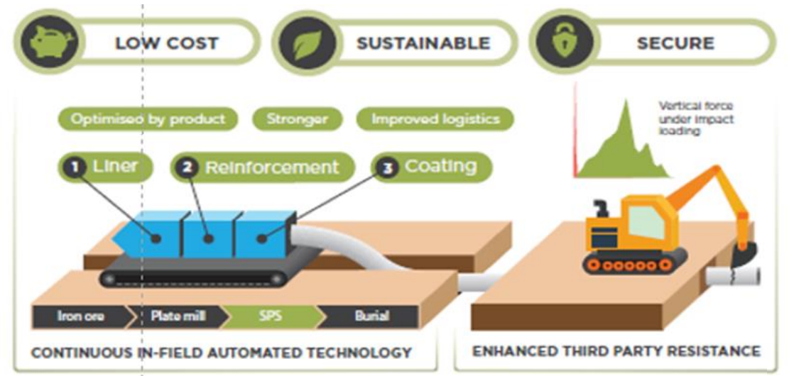
The pipe structure that enables MASIP is that of a pipe with four basic components to the wall of the pipe. Each performing a clear function. These are: A. Inner pipe liner, of a corrosion resistant material such as HDPE, providing fluid tightness and chemical resistance B. Reinforcement layer of spirally wound interlocking high strength steel strip, providing mechanical resistance to internal pressure C.
Spirally wound optical fiber, providing an in-built distributed sensing layer D. Environmental protection using tape wound polymer system, providing corrosion and abrasion resistance
Figure 1 shows schematically the automated winding machine modules that wrap the high-strength steel reinforcement on to a corrosion resistant liner and then wrap optical fiber and environmental coating and protection layers on top of that.
The resulting pipe is then laid directly from the back of the machine into a trench respecting the various engineering guidance parameters that have been developed. This type of pipe is inherently tougher, lighter and more flexible. It has been found that it is more resistant to excavator bucket impact and running cracks than conventional pipe.
A key feature is that the high strength steel reinforcement can absorb more impact energy before puncture occurs. In addition , if puncture does occur, then there is no running crack as the crack energy is dissipated by the strip design whereas in conventional pipe the energy to drive a crack increases with crack length causing a running crack that can become a major hazard. This pipe structure provides the basis for mobile automated spiral intelligent pipe (MASiP) (Figure 2).

In a pipe mill, ship it to a coating plant and then to the field site in 12-m lengths where they are welded together in labor intensive but well-established procedures. There are increasing problems with deploying labor intensive processes to build pipelines in remote areas in the conventional manner.
This has been highlighted by the COVID pandemic which has required new safe distancing and protective equipment protocols unrelated to the engineering procedures themselves. Introducing automated manufacturing equipment into the field that can produce continuous pipe has considerable advantages in any event, but these are accelerated by post COVID requirements.
Another advantage is that quality control can be automated as part of the process that combines manufacturing and installation. This greatly increases quality assurance and reduces the scope for workmanship defects being left behind in the pipeline to cause problems later. The pipe structure produced in this way is considerably more flexible than conventional pipe structure.
Pipe can be laid continuously to navigate 40 D bends in the terrain and this enables most if not all cold bend stations to be eliminated. This allows the machine to follow the terrain more closely.
The same pipe manufacturing machine can make pipe with a range of diameters and wall thicknesses. This would allow pipe to be adapted – for example if there were sections of terrain where a larger safety factor was to be required. This concept is designed to reduce pipeline construction costs by half or more, eliminate the need for labor intensive processes as well as dramatically reduce the carbon footprint of pipeline construction.
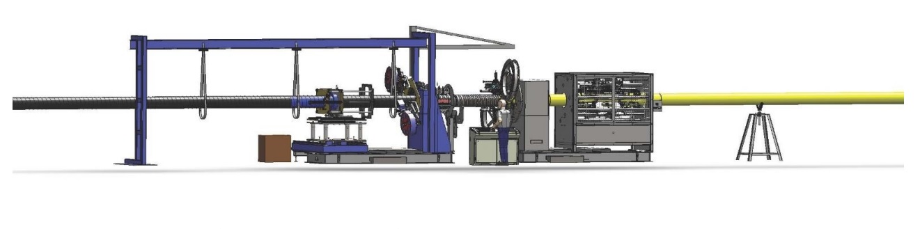
Another benefit is the reduction in construction time that automated processes bring. Pipe manufacturing Quality Control has been automated with digitized sensing and data recording of each key part of the process. The concept has been realized with detailed design of a full scale commercially viable prototype system (Figure 3).
The pipe is manufactured in situ from raw materials on the wayleave and incorporates spirally wound optical fiber to provide an enhanced level of real-time information about stress- strain patterns in the pipe.
The pipe consists of a polymer liner and reinforcing layers of high-strength steel strip with a patented interlock. The whole pipe is coated for environmental protection. This type of pipe structure is inherently more flexible and more responsive than conventional steel pipe structures.
Real Time Monitoring
An optical fiber-cable is spirally wound (Figure 4). This layout increases the length of fiber per pipe length, which provides a significant advantage in terms of spatial resolution. The structure of MASiP pipe provides a natural feature to accommodate the fiber-optic spiral which can enhance sensitivity but also makes the positioning of the cable more robust.
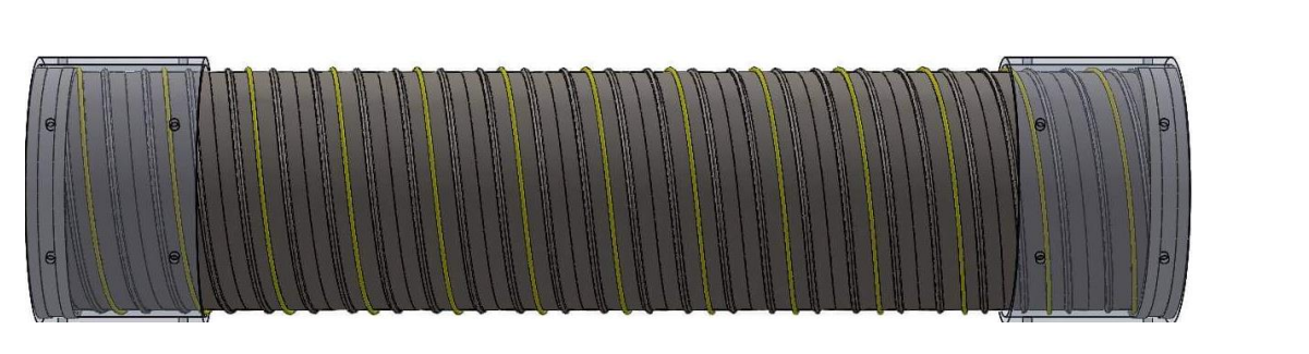
During pipe manufacture, the outer coating is applied over the top of the fiber and that also secures and protects the fiber. A flow loop was set up (Figure 5) to test this system. The flow loop included several pipe sections at 12-inch in diameter.
There were two MASiP sections, one 1.5-m long and one 3-m long, which were connected using standard flanges to four conventional standard elbows and one straight X52 pipe length which included two girth welds. Thus, a direct comparison could be made between the performance of MASiP and conventional steel pipe sections.
The overall length of the test loop was 6m and gas was supplied from accumulators so that pressure cycling could be conducted. The pressure range of pressure cycling for these trials was between 40 and 70 bar (580-1,015 psi). The gas mixes included nitrogen, methane, a hydrogen-methane mix and 100% hydrogen.
The pipe sections were also fitted with strain gauges and monitored with a parallel system so that the fiber-optic outputs could be monitored. All test witnessing was conducted remotely using a mix of video and data streaming tools that were available to the project engineers 24 hours a day for a month.

The DAS system works by means of light pulses that are then back scattered from naturally occurring defects in the glass to form an interference pattern which can be interrogated for either acoustic data or strain data.
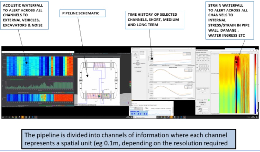
This approach is extremely sensitive to small stresses and strains in the wall of the pipe. A sensitivity of 2 microstrain has been measured during Stage 2 trials conducted during 2020. The resulting prototype dashboard is represented in Figure 6. One channel of information consists of about 1 m of fiber or 0.12 m of pipe length.
The strain outputs were found to be more informative for pipeline condition monitoring than the acoustic data – which was more informative for external events such as nearby truck movements or other indicators of third-party events.
The waterfalls provided color coded raw data across 1,000 information channels in real time. The red sections on the waterfall indicate activity. In addition to the waterfalls, for any group of channels the time history is displayed to the desired strain resolution with rolling short, medium- or long-term data.
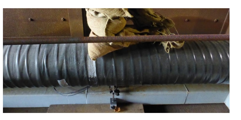
Test were conducted to see how sensitive the system was to displacements of the wall of the pipe. A series of sandbags were applied to the center of a 3 m length of pipe (Figure 7).
Vertical displacement of the pipe was directly measured by means of an accurately calibrated displacement gauge. For each of 4 successive 6kg sandbags the central displacement measured was 0.025 mm or 0.1 mm for 24 kg vertical weight.
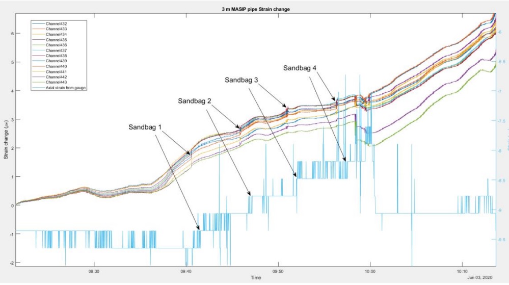
The fiber-optic outputs were distinctive steps increasing the train in the fiber (Figure 8). A strain change of 0.2µƐ was seen every time a sandbag was added. A similar strain was seen from neighboring strain gauges applied.
This shows that the system can determine exceedingly small strain changes in the wall of the pipe. It is considered that this system is up to 1000x more sensitive than any comparable system and responsive to the pigging challenges referred to above as well as providing a clear alternative to intelligent pigging.
Conclusions
A new approach has been developed and tested at full scale which has the potential to dramatically increase the sensitivity of pipeline integrity monitoring as well as offering real time data with good spatial resolution.
Digital fiber offers enable pigging to be carried out on an “as required” basis in response to changes detected in the pipeline and thus from a basis of being much better informed about what is going on in the pipe. Using the digital fiber takes away several the issues described with intelligent pigging.
There is no need for intelligent pig launchers and receivers. The information about the pipe from the inbuilt digital fiber-system is available in real time without having to wait for pig run results processing.
Cleaning pigs can still be used but the MASiP system provides real time monitoring information to accurately track and time the pig’s progression down the length of the pipeline. This potentially translates to significant cost and time saving on critical onshore or offshore pigging projects. Testing described in this paper has been focused on onshore issues and further hydrodynamic testing would be required for offshore applications to address installation and fatigue life risks offshore.
Acknowledgements: The authors would like to thank DNVGL Spadeadam test team for pipe testing and Optasense Ltd for managing the fiber-optic interrogation and data management. MASiP is a registered trade-mark owned by SPS Ltd.
Editor’s note: A version of this article was originally published as “Digital Pipeline Integrity Management – A New Approach” in association with PPSA Seminar 2020.
References:
Digital Automated Pipeline Construction – Stevenson, Everard & Bobat SPE-202988 ADIPEC November 2020
Hydrogen Compliant Automated Pipeline System – Stevenson, Everard & Bobat Gas International May 2020

Comments