
May 2023, Vol. 250, No. 5
Features
Using Resonance Technique to Test Pipeline Weld Fatigue
By Neil Trigwell, Engineering and Technology Director, Element Materials Technology
(P&GJ) — Steel catenary risers (SCRs) are a critical element within many offshore pipeline installations. The ability of these risers to withstand the installation and in-service loading is vital to the success of the projects in which they are used.
Offshore pipelines are critical and expensive items of infrastructure with the cost of each meter of installed length running into thousands of dollars.[1]
These pipelines often operate in harsh environments, and it is an economic and environmental necessity that they survive at least their full design life, which is typically around 15 years. The risers are a particularly critical part of the pipeline, especially catenary risers, which tend to have long, unsupported spans.
SCRs were first conceived in the late 1960s with a patent application being filed in 1971.[2] However, it was more than 20 years later, in 1993, before Shell pioneered implementation of the concept on the Auger tether leg platform.[3] Since that time they have become a major factor in our ability to commercially exploit deep-water fields.[4]
Because of their long, unsupported length, wind, wave, ocean currents and operating cycles can all impose cyclic loading on the SCR, creating a susceptibility for the formation of cracks through metal fatigue.
Fatigue cracks are particularly likely to form at surface, or near surface, discontinuities, making the girth welds joining the individual section of pipe potential crack initiation sites. It is essential that there is confidence that the welding process will produce welds that will exhibit the necessary level of resistance to the development of fatigue cracks.
Design Principles
The need to design against fatigue was recognized at the very onset of the planned use of SCRs. Consideration of fatigue in the design of critical metallic structures such as bridges had already been addressed and a methodology based on classifications of joint details developed.[5] These early approaches for addressing fatigue have been further developed into the design codes used today.[6-8]
The codes governing pipeline design and construction have a range of standard fatigue performance criteria. The pipeline designer will select the criteria most applicable to a particular section of pipeline. The criteria are normally defined as an S-N curve, where S represents the cyclic stress range and N the number of stress cycles of that amplitude that the pipeline must be able to withstand. The basic equation for an SN curve is as follows:
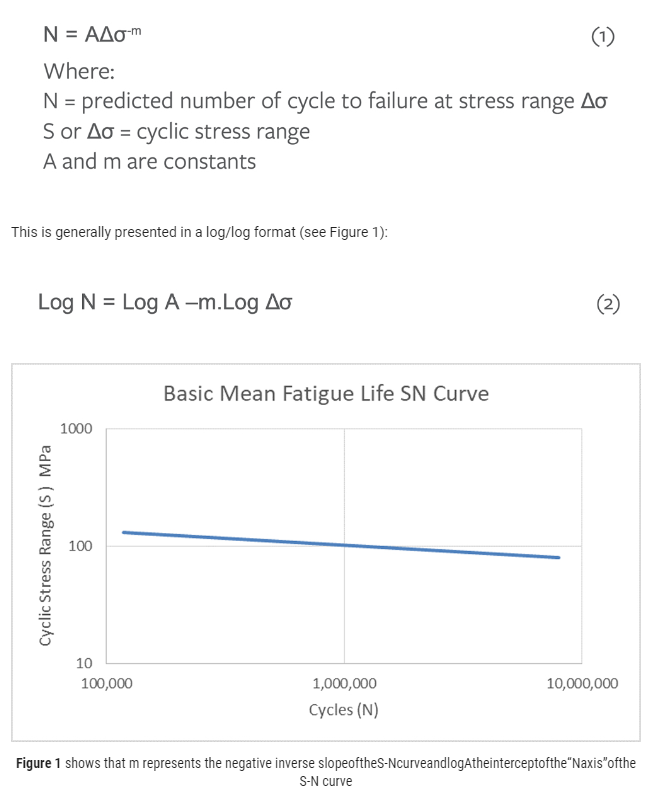
Figure 1 shows that m represents the negative inverse slope of the S-N curve and log A the intercept of the “N axis” of the S-N curve.
For design purposes, the S-N curve, defining the expected mean fatigue life of a population of welds, must be shifted to represent the expected lower bound performance. This shift is normally 2 standard deviations of Log N (corresponding to 97.7% confidence of survival) as follows:
The design curve selected also must be appropriate for the environmental conditions that the pipeline will experience, such as exposure to seawater, the influence of imposed potential from cathodic protection and possible corrosive effects of the product being carried by the pipeline.
In addition to basic material properties, the fatigue performance of a girth weld will be influenced by many factors. These will include the topography and geometry of the weld, misalignment, position relative to the weld stop/start and factors such as the residual stresses present from the welding process.
Because of the unacceptable consequence of failure of a girth weld combined with the number of potential influencing variables, confirmation of fatigue performance is as important as that for other mechanical properties verified as part of the weld procedure qualification. Since it is not possible to easily incorporate all these variables into small coupon tests, it is preferable to test complete girth welds to verify the fatigue performance of welds produced to a given procedure.[9]
Fatigue testing of metals in air is relatively insensitive to the frequency of cyclic stress over a broad range. This enables the collection of fatigue data for service in air to be accelerated by testing at higher frequencies than a structure or component may experience in service.
However, because environmental factors tend to have a strong time dependence, there is a limit to the extent that tests examining the effect of environment can be accelerated. Full-scale testing of girth welds at near real service frequencies would be prohibitively expensive and time consuming for anything other than fundamental research and development projects.
Coupon testing has been the predominant route used to determine the effect of environment on the fatigue life of welds. Results of these tests have been used to establish the relationship between the fatigue performance of welds tested in air to those tested in environment at near service frequencies.
These relationships are generally referred to as “knock-down factors.” They are considered in certain design codes (e.g., DNVGL-RP-C203), where a range of design curves are defined in air, with corresponding curves for performance in seawater with and without cathodic protection.
These knock-down factors enable a required level of fatigue performance in environment to be equated to a corresponding level of performance in air. This enables girth welds to be qualified for resistance to fatigue by testing in air at relatively high frequencies (i.e., typically between 25 and 35 Hz).
Test Programs
For a testing facility to successfully address a client’s requirements, it is essential to fully understand the objectives of the proposed test program. In the case of a fatigue test program on pipeline girth welds, many potential test variables need to be agreed to ensure that the objectives are satisfied.
Testing is usually carried out to qualify a specific girth weld procedure used to join lengths of pipe under a certain scenario and for a specific application. However, it may be to examine the fatigue performance of a specific feature, for instance in a corrosion resistance alloy (CRA)–lined pipe. The purpose also may be to assess the fatigue performance of the “triple points” between a CRA liner, CRA overlay and the carbon steel outer pipe.
In the more common cases of qualifying individual welding procedures, the number of different procedures to be evaluated will be project-specific. It may require different diameters of pipe to be tested and even different thicknesses (e.g., if thicker wall pipe is used in certain critical areas such as the touch down region).
It may be necessary to qualify both welds produced onshore and those to be carried out offshore where the procedures differ in respect of critical variables.
Knowledge of the pipe sizes and wall thicknesses are among the first parameters that need to be clarified because this information is required to calculate the test string length. This information will be relayed back to the client so an appropriate provision of pipe can be made for test purposes. Knowledge of any CRA lining or overlay is required to select the appropriate sealing methodology.
Test Strings
Test strings are prepared for fatigue testing by the pipeline fabricator using the exact procedure intended for the construction of the actual pipeline. It is common practice to deliberately introduce misalignment in the test welds, equal to the maximum permitted during fabrication so that worst-case stress concentration effects are incorporated in the test program.
The length of the test string is calculated to give a natural frequency of slightly less than 30 Hz using the Euler-Lagrange model. This calculation must take account of the mass of the rotary vibrator fitted to one end of the pipe and a balancing mass attached to the other. Element will feed back the proposed test string length as soon as the necessary information on pipe dimensions has been made available.
Test stings may contain a single or multiple welds. It is common to test strings with two welds per string where the test welds are separated with a central section of pipe (a pup-piece). In tests to verify the performance of welds to say a J-lay collar, the central pup-piece may be manufactured from forged material representative of the collar material rather than a section of the line pipe.
Three welds per string can be used to accelerate the test program, but it must be remembered that the stress distribution along the pipe is roughly parabolic; hence, the stress on the central weld will be slightly higher than that on the welds on either side.
If the pup-piece lengths are to be adequate to avoid excessive interaction between the welds, then trying to incorporate more than three welds will mean that there will be significant variation in the cyclic stress levels seen by the central welds to those at the extremes.
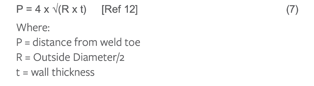
There is no definitive ruling regarding the length of pup-pieces used to separate welds, but lengths between 1.5 and 2 times the pipe diameter are usual. The influence of a weld has been shown to have dissipated by around 4 × √(R × t) from the weld toe,[12] where R is the outer radius of the pipe and t is the wall thickness, leading to a suggested separation of around 8 × √(R × t).
After producing the test welds, it is normal practice to inspect these using the same methodology and to the same standard as intended for use on the production welds to ensure they are fully representative.
Axial Mean Stress
The near resonance fatigue testing methodology introduces bending stresses in the pipe that are symmetrical around a zero mean stress (i.e., fully reversed bending). The degradation from fatigue at stresses below yield arises predominantly from the tensile portion of the fatigue cycle.
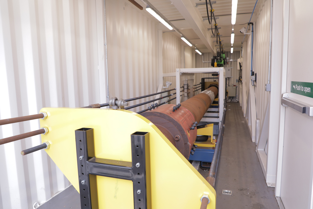
To induce fatigue cycles that are fully tensile, it is necessary to induce a constant axial stress in the pipe, which acts in addition to the cyclic bending stresses (Figure 2). This axial mean stress is generated by sealing the pipe with end plugs or caps that enable the pipe to be filled with water and then pressurized.
The mean stress is normally set at the same level for all the test strings in a procedure qualification. It is generally either related to the expected in-service static axial load on the riser or, more commonly, a stress level that will ensure the entire fatigue cycle remains in tension.
It is typically in the range from 100 to 130 MPa. The pressure required to produce the target mean stress is a function of the pipe diameter and wall thickness, and it is generally in the range between 30 and 150 MPa (i.e., 300 to 1,500 barg).
Element has two standard methodologies for sealing the test strings. For unlined carbon steel pipes, the preferred approach is to use internal plugs secured in place and sealed with fillet welds. For clad or lined pipes, it is more usual to seal the pipe using a plate-type end cap secured with a full penetration girth weld.
It is normal practice to limit the internal pressure such that the hoop stress generated is less than 90% of the material yield stress. For very thick walled pipes, this may necessitate the fatigue conditions on the bore of the pipe to be considered in isolation to those at the outside diameter.
As the cyclic loading is induced as a bending stress, the cyclic stress range at the bore will be less than at the outer surface. A fully tensile fatigue cycle can be achieved at the bore with a lower mean stress.
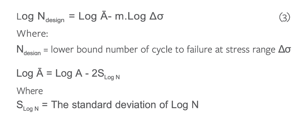
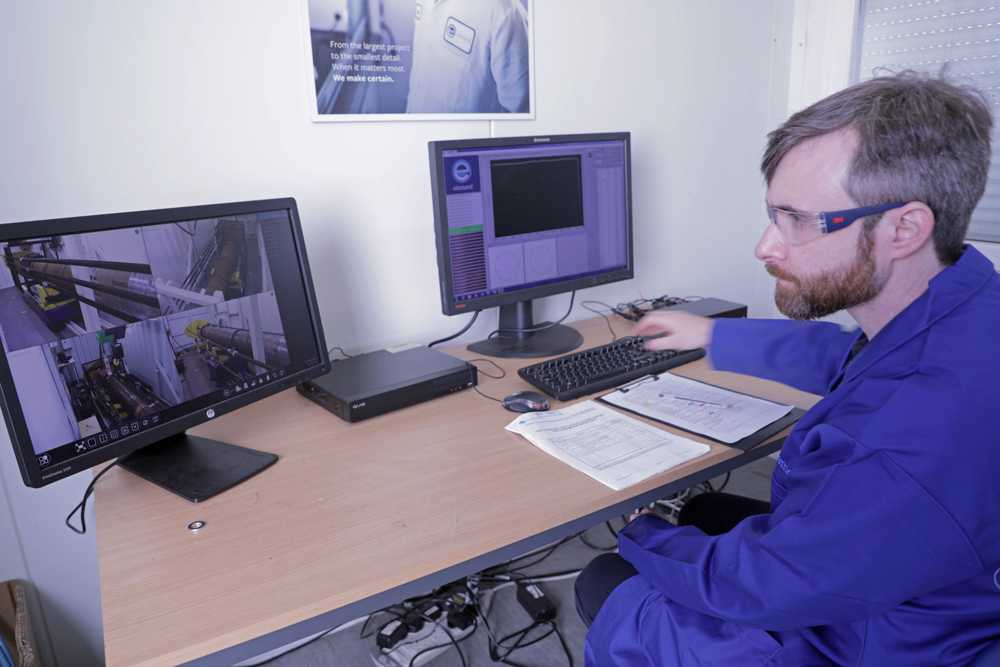
Hydraulic pressures involved in generating the mean stress and the associated stored energy require appropriate safety precautions to be in place. Test strings are always initially proof pressure–tested to between 110% and 120% of the pressure that is to be maintained during fatigue testing.
Multiple layers of safety containment are in place, and closed-circuit video monitoring minimizes the need for personnel to enter the test vicinity while the test strings are pressurized (Figure 3).
Number Of Welds
Testing is normally conducted using at least three different cyclic stress ranges to ensure that the fatigue performance of the welds exceed minimum requirements over the range of the relevant S-N curve. To qualify a weld procedure, it is normal to test between nine to 12 welds.
For a check or comparison of a procedure broadly similar to one already qualified, this number, with the agreement of the interested parties, may be reduced to six test welds.
The stress levels may be specified by the end-user specification but generally these should be set to give target endurances between 2.5 × 10⁵ to 1 × 10⁷ cycles. This range of endurances will provide adequate confidence that the welds will provide appropriate resistance to fatigue over the spectrum of the anticipated in-service loading cycles.
The resonance method is fundamentally unsuitable for tests where the string will approach yield because excessive energy will be adsorbed, which the rotatory vibrator will be unable to supply. Also, it is a method intended to input thousands of cycles.
If the pipeline is to be installed by reeling, it is usual to carry out simulated reeling cycles (which normally involves straining the test string well beyond yield) on a separate rig designed specifically for this purpose prior to preparation for fatigue testing.
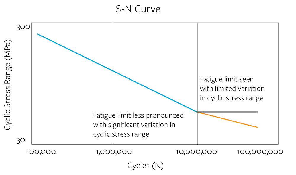
Testing at stress levels with target endurances significantly beyond 1 × 10⁷ cycles is considered of limited benefit. The fatigue curves for steels tested at a constant stress amplitude tend to reduce in slope significantly beyond this endurance.
This means that fatigue lives can increase very significantly for only a small change in the cyclic stress level (the fatigue limit effect). Data collected in this regime have limited practical application because this change of slope is an artifact of testing at constant amplitude or within a narrow band of stress amplitudes. The effect may not be observed under service conditions if there is a significant variation in the amplitude of the cyclic stresses (Figure 4).
In some end-client specifications, the target endurances may be set as simple multiples of the design line endurances. Separate endurances may be set for the minimum fatigue life exhibited by each individual test weld and the mean fatigue life displayed by the full set of test welds.
Other end-client specifications require target endurances to be calculated that will demonstrate that the design curve requirements have been met or have exceeded with a specified statistical confidence. In these cases, the target endurances will depend upon the number of welds being tested.[6, Appendix E]
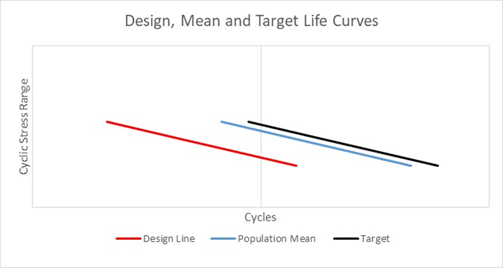
As discussed previously, the design curves are lower-bound curves, typically with the endurance shifted to 2 standard deviations lower than the expected mean lives for that class of weld. The mean endurance curves apply to a large sample population. Mean life S-N curves, through small samples of data drawn from the larger population, will be distributed around the whole population mean curve as follows:
To ensure that the population mean curve is exceeded by an appropriate margin, the target endurances are set above the mean curve by the inclusion of a factor f.Ss as follows:
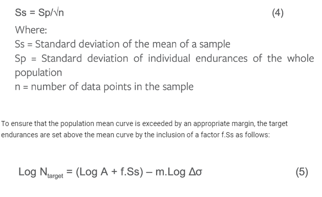
Where f is the inverse of the standard normal cumulative distribution for the required confidence interval (i.e., for a 95% probability that the population mean is equal to or exceeded f = 1.645) (Figure 5).
Although target endurances are based on the means of both the class population and sample of welds tested, many specifications require all welds tested to exceed the target endurances. This simplifies any further calculation but adds additional conservatism above the stated confidence level.
It is critical to ensure that the location at which the required cyclic stress applies is clearly identified. This may be in the region adjacent to the weld (i.e., within any counter-bored region), on the nominal full wall thickness (i.e., outside any counter-bored region) or may apply to either the outside or inside diameter.
The effect of any counter-bore or section change close to the weld on the cyclic stress range can be estimated by considering the second moments of area in this region relative to that of the pipe at the nominal wall thickness:
Instrumentation
The cyclic stresses induced in the test welds are measured by the application of bonded electrical resistance strain gauges (Figure 6).
These are attached to the outside surface of the pipe in rings around the pipe circumference at a defined distance from each weld. An end-client specification often defines the number and placement of the strain gauges.

Rings of four or eight gauges are commonly used. The use of rings of eight gauges are recommended where there may be significant ovality or on diameters over 14 inches (350 mm). These may be placed one side of each test weld, both sides of each test welds, or in rings on the outboard side of welds and on the centerline of any pup-pieces.
Opinions vary on the preferred placement of strain gauges, often in part based on how the relevant cyclic stress levels are defined. Some specifications require the gauges to be positioned relatively close to the welds (typically around 2 inches [50 mm]). Other specifications prefer the gauges to be positioned further from the weld, away from any direct influence it may have on the local stress level for instance.
Gauges on either side of the weld are used to interpolate the cyclic stress range at the weld location. In these situations, consider the potential influence that the thickness transition of any counter-bore may have, so gauge placement needs to ensure that adequate distance is also left to the end of any such change in the internal diameter. Other specifications may require the gauge placement to be outside of any counter-bored region, so measurements are made on the full wall thickness.
It is important that the client provides details of the extent of any counter-boring, ideally by marking the end of counter-bores on the test string pipe lengths prior to fabrication; otherwise, these need to be detected by means of ultrasonic thickness measurements prior to instrumentation.
During testing the output from these strain gauges is monitored continuously and used to calculate the cyclic stress at the weld, averaged around the circumference. The software used to monitor and control the test system automatically adjusts the speed of the rotary vibrator to establish and maintain the required cyclic stress range.
The software will automatically stop the test once an agreed number of stress cycles have been exceeded or when a through wall crack (TWC) has developed. A drop in the internal hydraulic pressure detects this, as well as sensors that detect the presence of water in catch trays placed beneath the test welds.
In certain situations, the cyclic stress distribution around the pipe may be observed to be uneven. This may arise if the test string is not straight if the pipe has significant ovality (e.g., following simulated reeling) or has significant variation in wall thickness around the circumference.
In these situations, it is generally possible to improve the uniformity of the cyclic stress distribution. This is accomplished by coupling mass to the non-driven end of the test string through a mechanism that is rigid to movement in one direction normal to the longitudinal axis of the test string but hinged to movements 90 degrees round from the rigid direction.
This additional mass has the effect of reducing the natural frequency in the plane of the rigid coupling, increasing the cyclic stress amplitude seen in this direction.
Test strings are normally instrumented to include temperature. Additional instrumentation can be provided on a project-specific basis. For example, this may include additional strain gauging or water sensors for monitoring the performance of lined pipe where the fatigue performance of internal features may be of as much interest as that of any girth welds.
Termination Criteria
It is common practice to run at least one test weld at the highest stress level until a TWC is developed. This provides some indication of how the actual performance of the welds compares with the target endurance.
Clearly the confidence in this indication increases with more welds run to the point of TWC development; however, there are practical limitations. Because of the logarithmic nature of fatigue, welds performing significantly better than the design class requirements could exceed the target endurances by an order of magnitude, especially at intermediate and lower stress levels.
Test strings not designated to be run to TWC development are generally stopped once the target endurance is exceeded by an agreed margin (i.e., a run-out endurance). This margin is usually between +20% and +100% of the target endurance.
The viability of testing to TWC development of welds at intermediate stress levels will depend upon the actual cyclic stress range and target endurance. It is recommended that even when TWC development is requested for strings tested at intermediate stress levels, some run-out endurance is agreed, albeit with a higher margin over target than for the lower stress levels.
An alternative strategy would be to increase the cyclic stress range once beyond, say, 1.5 times the target endurance. Miner’s rule and the assumed slope of the S-N curve can then be used to provide an estimate of the additional cycles that might have been expected had the cyclic stress range been left at the original value.
If the endurance at intermediate stress levels exceeds the target endurance for lower stress levels, considerations should be given to adjusting the stress levels for remaining tests strings. Low stress range tests run to shorter endurances than medium stress range tests and may satisfy contractual obligations but provide limited performance data.
Post-Test Examination
Following testing it is common practice to extract the test welds from the test strings to facilitate some level of examination. Specifications differ on the post-test examination requirements. Generally, all welds will be examined visually and using either fluid penetrant inspection or magnetic particle inspection to check for the presence and circumferential extent of any cracking.
Thickness and misalignment measurements are also usually performed. Specifications vary as to whether this is on all welds or only those where a TWC has developed. Clearly, having this information for all welds tested can provide a valuable insight into the potential influence of factors such as misalignment and eccentricity.
These data permit the calculation of stress concentration factors (SCFs) around the weld. There are several industry-recognized equations for calculating the SCF,[13,14] and these generally reflect the effect of parameters such as high-low and thickness change on either side of the weld. They do not usually incorporate factors related to the actual weld profile. The equation to be used to calculate any SCFs, if required, should be agreed upon with the client.
Welds containing any TWC are generally sectioned and examined metallographically to try to identify any feature that may have promoted fatigue crack formation.
In cases where the fatigue performance of a weld has been unexpectedly poor, this examination can be extensive and include the use of scanning electron microscopy and energy-dispersive X-ray chemical analysis (EDAX). An example of where this additional examination capability has been deployed was an instance where a brittle near surface area of a weld was observed to have cracked, which led to the premature formation of a fatigue crack. The reason for the presence of the brittle area was traced to copper pick-up during welding.
Future Development
While existing resonance fatigue methodologies provide an effective solution for current girth weld fatigue validation, it is essential to look ahead to prepare for new challenges facing the oil and gas offshore sector.
The need to verify the fatigue performance of pipeline girth welds is not limited to just SCRs; the requirement can apply to any critical section of pipeline subject to cyclic loading.
Frequently, however, in these other critical sections, fatigue loading is often service-induced, and the loading spectrum is dominated by higher cyclic stress levels with fewer cycles. The resonance technique is not suitable for cyclic loading beyond yield; for low cycle fatigue, other testing methodologies are more applicable.
Test programs using the resonance methodology focused at the higher end of the elastic regime of the S-N curve, however, may still be of value in these situations. This requires very precise control of the excitation frequency and higher levels of energy input, because even in a predominantly elastic stress cycle, at high stress ranges, some micro-plasticity is to be expected. Continuous development of our test systems ensure that Element is well placed to handle these challenges.
In regions where trends are toward deeper, higher-temperature and higher-pressure wells, SCR designs often specify thick wall pipe.[16] In addition to increasing test string weight, this potentially introduces some complications to defining the test parameters.
Increased wall thickness requires higher internal pressure during fatigue testing to create the specified mean stress. However, the thick wall can mean that bending stresses in the hoop direction resulting from pressurization could bring the internal diameter close to yield, which should be avoided.
This, combined with the gradient in the cyclic stress range through the pipe wall, may make it necessary to consider the performance at the outside diameter separately to the bore. Measures may need to be taken to prevent initiation at the cap to ensure performance at the weld root can be established. Eccentricity of the bore is also more likely in these thicker wall pipes, which will increase the need to use techniques to correct the stress distribution around the pipe.
The use of internal lining of pipes is also expected to increase, allowing economical exploitation of more aggressive fields. New approaches to joining liner sections will require validation and are expected to introduce new challenges for in situ monitoring.
Element have already looked at the design of resealable end caps to simplify and speed up periodic internal inspections. Developments in sensor technology are also monitored, which may be relevant to meeting forthcoming challenges in respect to inspection and failure detection of liners.
It is possible that the industry may even see the use of non-metallic SCRs[15] or polymeric liners. Again, joints are likely to prove critical from a fatigue perspective. Testing rigid non-metallic assemblies in the high-cycle fatigue regime using resonance technology may be possible provided that any adiabatic heating effects are small or can be adequately dissipated. It is more applicable to composites rather than pure polymeric systems.
Rotary vibrators currently used are a simple and highly effective means of exciting the test string into resonance. It is recognized, however, that more complex units can provide additional benefits, by providing differing levels of excitation in specific directions around the longitudinal axis of the test string.[16]
While this can already be accomplished with the methods described earlier, modern technology may permit adjustment of the strain distribution to be fully automated under closed-loop control. Developments in this area may permit the testing methodology to be extended to structures that are not axisymmetric.
Author: Dr. Neil Trigwell is a chartered engineer with more than 40 years of experience in materials testing. He obtained his PhD through research into the application of fracture mechanics to high-temperature crack growth.
REFERENCE
- Kaiser, M.J., Marine Policy 82 (2017): p. 147-166.
- Langner, C.G., R.C. Visser, “Method of Connecting Flowlines to a Platform,” US Patent 3,669,691, filed Feb. 8, 1971, issued Oct. 24, 1972.
- Yong Bai, Qiang Bai, Subsea Engineering Handbook (Second Edition), Chapter 30.1.1, “Subsea Production Risers” (Gulf Professional Publishing, 2019).
- Mekha, B.B., J. Offshore Mech. Arct. Eng. 124, 4 (2001).
- British Standards Document BS 5400-10, “Steel, concrete and composite bridges. Code of practice for fatigue,” https://doi.org/10.3403/01690231U.
- British Standards Document BS 7608:2014+A1:2015, “Guide to fatigue design and assessment of steel products.”
- DNVGL-RP-C203, 2016, “Fatigue Design of Offshore Steel Structures.”
- AWS D1.1/D1.1M:2015, “Structural Welding Code – Steel.”
- Maddox, S.J., Y-Hui Zhang, Proceedings of the 27th International Conference on Offshore Mechanics and Arctic Engineering, June 2008, Estoril, Portugal.
- Kerkhof, K., W. Stoppler, D. Sturm, R. Zim, Nuclear Engineering Design 119 (1990).
- Buitrago, J., M.S. Weir, W.C. Kan, Proc Int Conf on Offshore Mechanics & Artic Engineering, June 2003.
- Darcis, P., et al, Proceedings of the ASME 2009 28th International Conference on Ocean, Offshore and Arctic Engineering, OMAE2009- 79811.
- Connelly, L.M., N. Zettlemoyer, Proc. of Intern. Symp. Of Tubular Structures, Nottingham, UK, August 1993.
- DNVGL-RP-F108, 2017: “Assessment of Flaws in Pipeline and Riser Girth Welds,” 2017, Section 4.3.5.
- Simpson, P., A. Lima, Offshore Technology Conference, Brasil October 2019.
- Wang Chuan, Hongwu Zhu, Dingya Wang, Journal of Applied Science 13, 6 (2013): p. 854-861.

Comments