March 2024, Vol. 251, No. 3
Features
Pipeline Movement, Landslides Navigated with Technology
By Daniel Bahrenburg, Senior Engineer, ROSEN Group
(P&GJ) — Bearing the responsibility of ensuring the continuous flow of energy resources through vast networks of pipelines, the custodians of pipeline integrity face an ever-present challenge: geohazards.
From seismic shifts to landslides, these relentless forces pose an intriguing and formidable threat that demands our unwavering commitment to safeguarding the arteries of energy transportation.
In response, ROSEN and Teren have leveraged modern technologies and methods to devise a solution that supplements standard geohazard management approaches with unparalleled efficiency.
Join the front lines of the unseen battles beneath our feet, where the fusion of engineering precision and an innovative strategy is redefining the way in which we manage and mitigate the likelihood of geohazards impacting our pipeline systems.
LiDar and AI
Using LiDAR data to detect landslides and landslide potential is not a novel concept. LiDAR has been widely valued by pipeline operators and integrity consultants for geohazard identification, and it is now a key tool for geotechnical experts assessing pipeline rights-of-way.
But how do we leverage modern technologies to ensure we are extracting maximum benefit from this data? The growing prominence of artificial intelligence (AI) has allowed for the development of a data-driven approach to significantly increase the efficiency of geohazard assessments in order to reduce timelines and scale the assessment process to a size that effectively meets operators’ needs.
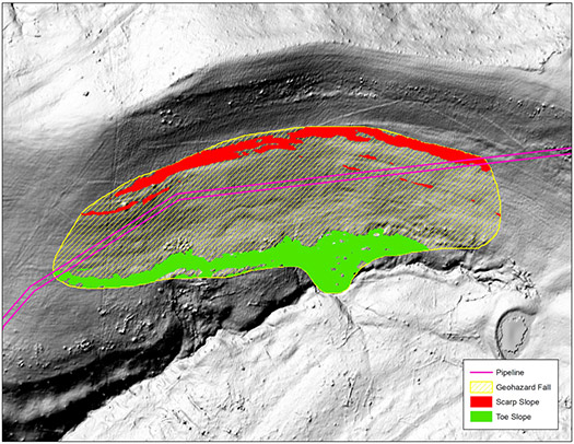
Computer vision algorithms can detect geohazards within the pipeline right-of-way automatically based on the following variables:
- Geohazard distance from the asset
- Degree of geohazard intersection with the asset
- Directionality of scarp and toe slopes movement in relation to the asset
- Steepness of the slope the geohazard is on
- Geohazard shape (round or oblong)
- Geohazard distance from the asset
- Geohazard size
Additional algorithms can then be implemented to characterize the structural components of the hazard, and a manual review is performed by an expert analyst to finalize their extents and remove false calls.
Using multiple LiDAR datasets, subsequent algorithms can be used to automatically identify changes to existing geohazards over a given time interval (e.g., land movement). Using a set of change detection analytics, identified ground movement can be due to:
- Remediated geohazards, including landslides that were present at Time 1 and absent at Time 2
- New geohazards, including landslides that were absent at Time 1 and present at Time 2
- Persistent geohazards that exist at both Time 1 and 2; these are evaluated for change to the body of the slide, scarp and toe slope migration, and distance from the asset
An example of this change detection process (Figure 1). Material added is signified by the green-shaded areas and material removed by the red-shaded areas.
While the proposed approach for identifying bending strain anomalies and coincident landslides boasts significant benefits, it also contains inherent limitations. For hazards identified as severely affecting the pipeline, additional assessments are required.
Inertial Measurement
Using inertial measurement units (IMU) to detect regions of bending strain and pipeline movement has been widely adopted by the pipeline industry. The popularity of this approach continues to grow, primarily due to its efficiency and effectiveness. Because almost any in-line inspection (ILI) tool can be equipped with IMU, it is easy to integrate and perform post-ILI functions.
The IMU does not measure bending strains directly. Rather, it measures differentials in the unit’s orientation relative to a calibrated starting position. The orthogonally mounted accelerometers and gyroscopes measure linear and rotational accelerations across six degrees of freedom, allowing the position (pitch, roll and yaw) of the tool to be determined in three-dimensional space.
This method assumes that the pipe begins as a straight segment and that any change to the pipeline trajectory is due to cold-bending of the pipe. It does not account for nonhomogeneous materials or changes in the shape of the pipe cross-section.
Once these calculations are performed, the entire pipeline can be screened for bending strain anomalies using a predetermined set of criteria. This typically includes a required length, maximum strain and pattern characteristics that indicate unintended bending of the pipe.
When two or more datasets are available, it is possible to compare strains across a defined length of time and determine whether pipeline movement has occurred across that interval. When trajectory information is accessible, it is possible to tie two IMU datasets together at a localized interval to determine the magnitude of movement that has taken place in an area of concern.
Advantages, Constraints
By combining these independent assessment methods, a powerful and highly efficient framework emerges that can effectively support geohazard management programs everywhere.
Pipeline operators are able to determine – with lower resource expenditure than ever before – not only whether a landslide exists within the right-of-way but also whether it has affected the pipeline. As with any engineering process, advantages and constraints both exist.
An important distinction between the proposed method of geohazard detection and the conventional right-of-way geohazard review is the time, level of detail and final product provided to the operator.
Leveraging modern data processing speeds and computer vision AI shortens the timelines and reduces expert availability requirements. LiDAR can be acquired, geohazards identified and characterized automatically, and quality checks performed. This means the geohazard assessment does not constrict the proposed assessment process.
Because errors within an AI program are systematic, they can be identified and corrected as this service approach matures. A single geotechnical expert can review the results of multiple lines in a fraction of the time required for a standard manual geohazard assessment, reducing both the time required and the likelihood of human error.
The application of IMU bending strain analysis allows for hazards not currently impacting the pipeline to be specified as lower priority and not needing immediate intervention while identifying high-priority areas requiring a follow-up review. Lastly, the efficiency and ability to scale this approach for entire pipeline systems is unmatched by its manual counterpart.
Nevertheless, automation of geohazard detection has constraints. Because geohazard identification is automated, it is possible that some hazards may be overlooked by the program. The assessment process is limited to characterization, severity and prioritization, so recommendations for high-priority areas still require expert insight to determine whether remediation or further assessment is required. Additionally, advanced assessments need to be carried out for high-priority areas by a geotechnical expert as well.
Nevertheless, the benefits of using this approach to supplement any geohazards management program are apparent – as long as it is applied appropriately. It is of paramount importance that the details outlined above be examined during the planning stage and implemented during execution and review.
It should be noted that IMU bending strain analysis can also be applied with similar results to a more conventional approach.
Case Study: Products Pipeline
Using the methods and assumptions outlined above, this assessment process has been applied successfully to real-world data for areas of historical landslide activity. Let us take a look at a 16-inch refined products pipeline located within the Kanawha section of the Appalachian Plateau in Eastern Ohio. This pipeline was installed within the banks of a historical mining impoundment dam.
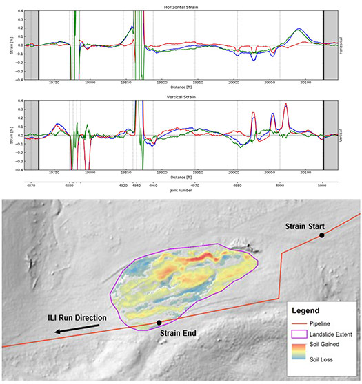
The top panel of Figure 3 presents a comparison of the bending strains calculated for two in-line inspections equipped with IMU. Strains are displayed as percentages. The first inspection, indicated by the red line, took place in 2016. The second one, indicated by the blue line, took place in 2022.
The green line is the calculated difference in strain between the two inspections. The results in both vertical and horizontal planes show that strain change (e.g., pipeline movement) has occurred. The horizontal plane reflects a somewhat characteristic movement response pattern. The vertical plane reflects a significant strain change as well, although with less consistent quality. This is likely due to the orientation of the landslide relative to this span and the 90-degree change in centerline trajectory occurring within the landslide area.
Based on the observed changes in strain and the specified sign convention, movement has occurred to the right and downward when observing the pipeline from upstream to downstream according to the direction of the ILI.
The bottom panel of Figure 3 shows the vertical change in terrain (soil movement) for the landslide between spring 2020 and fall 2021. The landslide is outlined in purple; the warm tones are areas of soil gain, and the cool tones are areas of soil loss.
Investigation of this site indicates that the landslide is active with a significant amount of change at the toe slope, and that it is moving downhill and to the right of the pipeline (red line). The change detection of the toe slope (lower right of the landslide) shows the largest amount of vertical soil gain.
Based on Teren’s ranking algorithm, this feature was classified as a 6 on a scale from 1 to 10, with 10 being the highest ranking. This ranking was assigned because the scarp slope intersects the pipeline (end point), is moving away from the pipeline (downslope), is relatively large (0.5 acres) and is on a gradual slope (17 degrees).
The results of the IMU-based pipeline movement and LiDAR-based geohazard assessments are in strong agreement. Based on the time intervals over which the two datasets were collected, it is possible to attribute causation. In addition, it is possible to quantify the amount of pipeline movement that has taken place as well as to determine the characteristics of the landslide.
Although additional material limit calculations and a coincident anomaly review would be recommended during the prioritization stage for cases like this one, the presence of active movement of both the ground and the pipeline are key indicators that remedial interventions are likely required for this site.
Advancing Forward
The presence and influence of geohazards pose many pipeline integrity challenges because of the increased frequency of soil-mobilizing extreme weather events, public awareness and regulatory requirements. As concerns regarding ground movement and pipelines continue to grow, finding efficient and scalable solutions will be demanding.
With powerful analytical tools at their disposal, integrity personnel can be equipped with modern methods of identifying and tracking geohazards, leveraging highly efficient processes and emerging technology. Landslides can be detected using LiDAR digital terrain models and AI analysis, while pipeline movement can be revealed using IMU-equipped in-line inspection. In tandem with these measures, additional checks against material limits and interactions with other pipeline anomalies allow for the efficient and informed prioritization of areas where movement has been detected.
As the pipeline industry continues to adapt and grow to meet modern challenges, such strategies will be required to ensure the safety of operational assets.


Comments