July 2019, Vol. 246, No. 7
2019 P&GJ Metering & Measurement
Using Computational Fluid Dynamics When Equipment Fails
By Mark Laing, CFD Service Leader, TÜV SÜD National Engineering Laboratory
The importance of accurate measurement cannot be under-estimated. In 2012, the oil price was above $100 per barrel, but only a year later, as oil prices began to decline, the average price of a barrel of crude oil was $91, dropping to $42 by 2015.
This reduction led the global oil and gas industry to reduce investment, with fewer new offshore rigs being constructed and the number of shared pipelines increased.
In the United Kingdom, this change in operator activity was well summarized as in a Wood Group report that recommended operators “focus on maximizing economic recovery for the U.K., as well as pursuing their individual commercial activities.” It also called for greater constructive collaboration between operators.
This has led to several “small pools” and marginal wells in the North Sea being developed which, due to the costs involved to build the required infrastructure, would not have been economically viable.
This means accurate allocation has never been more essential than it is now. Consider a situation in which multiple operators are transporting fluids via pipelines over large distances. Each operator must be allocated the correct portion of the total transported fluid at the outlet of the pipeline, but this is far more complicated than it sounds.
For example, if three different operators are transporting produced fluids via pipelines, it is normally the case that each operator will meter the fluids. The total flow in the co-mingled pipeline will also be metered and then the allocated fluids at the other end of the process will be metered by each operator.
The situation is complicated further because flow meters have a measurement uncertainty, and it is likely that each operator will have a different measurement uncertainty from their respective metering systems. As a result, there are various allocation philosophies and a complete review of uncertainty methods.
Among the most popular approaches in use: proportional-based allocation (highest uncertainty), base on difference and uncertainty-based allocation (UBA).
In recent years, we have undertaken computational fluid dynamics (CFD) modeling to resolve metering disputes between major operators pumping produced fluids via co-mingled pipelines to provide clarity on how revenue should be apportioned.
For example, an orifice plate is a differential-pressure (DP) flow meter in which the flow rate is proportional to the measured differential pressure. The standard for DP flow measurement, which includes orifice plates, is ISO 5167.
TÜV SÜD National Engineering Laboratory played a significant role in the development of the standard. The purpose of ISO 5167 is to ensure the fewest possible metering errors when using differential pressure flow meters and making this data available to industry to ensure consistency.
The performance of an orifice plate, as a flow meter is significantly affected if it is installed eccentrically, bent or buckled, or installed backward. This becomes a major issue if an orifice plate is being used to meter produced fluids from multiple operators in a co-mingled pipeline. On inspection, it is common for orifice plates to have been installed incorrectly.
Often it is very difficult to determine the measurement error from such situations. In the case of a buckled Orifice Plate it may take a large force to remove the plate from the carrier, which on occasion can damage the sharp edge and impact testing. In the case of an eccentric orifice plate it can also be difficult to seal the plate depending on the degree of eccentricity (sometimes flow even passes under the plate if it is eccentric enough).
CFD is a powerful tool for such applications and has proved to be extremely accurate. In order to determine the flow measurement error for such a meter, it is necessary to use CFD to compute the discharge coefficient for an ideally installed orifice plate. Next, compare this to the calculated discharge coefficient for the incorrectly installed orifice plate. The shift in discharge co-efficient can then be used to determine the flow measurement error.
Typically, when such simulations are undertaken the idea case is compared to the discharge coefficients outlined in ISO 5167 to gain an understanding of how well the CFD simulations represent the fluid behavior. Our research has shown that differences of 0.4% and less are achievable when comparing the ideal CFD case to the standard which is about 0.2%.
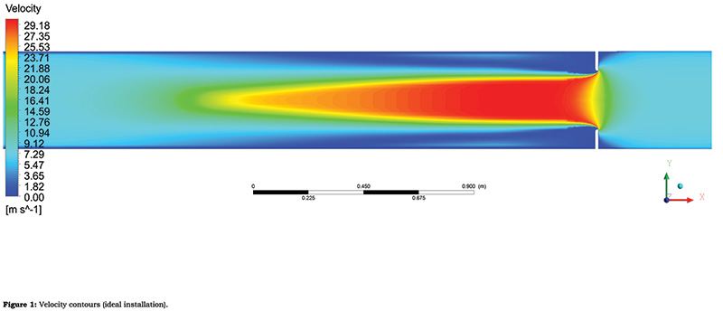
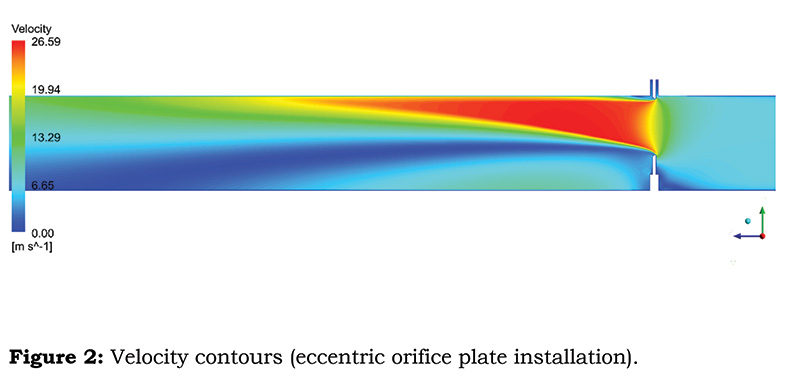
An example of the velocity contours for an ideal orifice plate (Figure 1) and for an eccentric installation (Figure 2). In this example, the eccentric installation is exhibiting a Coandă effect in which a high-velocity jet passing through the orifice becomes attached to the wall, contributing to significant measurement errors.
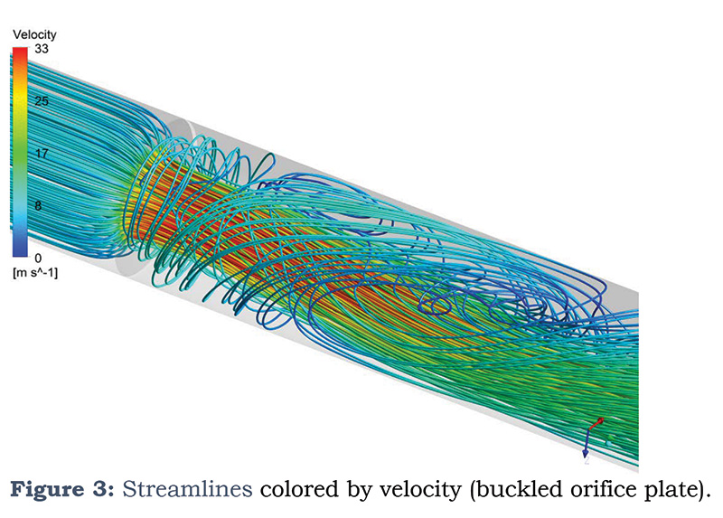
Figure 3 shows streamlines colored by velocity for a buckled orifice plate. There is significant recirculation after the orifice plate, which is undesirable. The magnitude of this will depend exactly where the tapping points are located. However, the measurement will be affected. As always, the validation of the modeling processes is key.
In addition to incorrect installation, erosion can also affect the accuracy of flow measurement, particularly differential flow measurement as the meters are intrusive. The types of meters likely to be affected are orifice plates, Venturi tubes and cone meters. These meter types are still regularly used in single phase fiscal metering applications around the world and therefore being able to quantify the flow measurement error resulting from erosion during their operational life is important.
CFD has advanced significantly in the last few years, particularly in the area of erosion. New techniques are available that make use of moving/deforming meshes to deform the geometry being modelled during an erosion simulation which is much more representative of field life. Often when sand is present in pipelines, sharp corners are rounded quickly, and this can affect the flow significantly. For example, the flow might separate where a sharp edge is present and then once this edge becomes rounded the flow no longer separates.
It is clear to see that once erosion begins to occur directly downstream of the cone meter, the pipe diameter is essentially increased. This means the beta (the ratio of areas) changes. Since beta is one of the key parameters used to determine the discharge coefficient for the cone and hence the flowrate it follows that the flow measurement will be directly affected. Using CFD it is possible to predict the erosion rate from simulations which can be subsequently validated. From this information, the flow measurement error can be obtained.
In summary, CFD is an incredibly powerful tool which is used extensively in the Oil & Gas industry as well as almost every other engineering sector. It can be used to quantify flow metering errors due to incorrect installation, damaged equipment, erosion and can bridge the gap very well between what can be achieved in laboratory testing to the much more extreme conditions faced in a subsea environment. P&GJ
Author: Marc Laing is the CFD service leader at TÜV SÜD National Engineering Laboratory, a provider of technical consultancy, research, testing and program management services.


Comments