
January 2020, Vol. 247, No. 1
Features
Managing Selective Seam Weld Corrosion as Part of Integrity Management Plans
By Simon Slater, Principal Integrity Engineer, ROSEN Integrity Services
The industry expects that all operators take a robust approach to integrity management, resulting in safe and reliable pipelines. One of the many known threats to pipeline integrity that must be explicitly addressed is Selective Seam Weld Corrosion (SSWC). This article explores ways of reliably assessing pipelines for the threat of SSWC and actively managing SSWC when it is an active threat.
For many years, pipeline safety regulations in the U.S. have defined prescriptive minimum requirements for integrity management combined with a clear expectation that operators should do more than the minimum where appropriate. The regulations have also provided operators with the flexibility to take a performance-based integrity management approach, enabling the deployment of resources to be optimized.
The recently published integrity management rules for gas transmission can be interpreted as requiring that threats must be explicitly discounted through data integration, risk assessment and line history. One of those threats that must be explicitly discounted (confirmed as “not present”) or assessed (defects identified, mitigated and managed safely) on a pipe segment is Selective Seam Weld Corrosion (SSWC).
Conventional responses to potential or identified threats have focused on in-situ investigations, often resulting in expensive and unplanned excavations and repairs for features reported by In-Line Inspection (ILI) that, when assessed, effectively demonstrate a remnant life well into the next inspection interval. When ILI identifies metal loss indications co-located with the longitudinal seam weld, the current prescribed response for liquid lines appears to be a blanket call for remediation, regardless of whether the metal loss is SSWC or “general” corrosion crossing the weld without any selective or preferential component to it.
It is recognized outside of formal regulations that the response to SSWC must be different from the response to “general” corrosion. As such, operators are looking at ways a differentiation can be made. This requires the deployment of an appropriate ILI system and integrity assessment. Multiple ILI systems are now available to detect, identify and size critical flaws associated with longitudinal seam welds. Well-understood engineering assessment methodologies using representative material data allow for fully informed decision-making.
Linear Corrosion
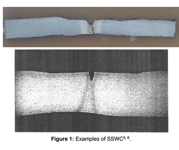
SSWC is an environmentally assisted mechanism in which there is an increased degree of metal loss in the longitudinal weld in comparison to the surrounding pipe body and is a pattern of linear corrosion that is centered on the longitudinal weld seam of welded pipe. An appropriate definition is linear corrosion that is deeper in the longitudinal weld zone than the surrounding pipe body. In some cases, the surrounding pipe body may have limited or no corrosion present, and in other cases the pipe body corrosion may have occurred but at a slower rate than the local corrosion in the longitudinal weld zone.
SSWC tends to have a relatively high length-to-width ratio and a localized area of maximum depth, described often as a V-shape (Figure 1). SSWC is most commonly observed in the bond line of autogenously welded pipe, such as electric resistance welded (ERW) or electric flash welded (EFW) pipe1, 2, 3.
The literature shows that a number of factors may be responsible for promoting SSWC1,4:
- A galvanic reaction between the base metal and the seam weld
- Differences in corrosion rates for different steel phases
- Inclusions and chemistry segregation in the weldment
- Crevices formed between inclusions and steel
- Sulphur enrichment
- Absence of an appropriate post-weld normalizing heat treatment
Many of the factors detailed above are commensurate with vintage pipe manufacturing and vintage steels, which as a result tend to be more susceptible to SSWC than modern pipe.
Corrosion Susceptibility
When managing SSWC, it is important to consider susceptibility. One of the first steps in determining susceptibility to SSWC is to confirm the type of pipe. This information may be available from original purchasing records, Mill Test Records (MTRs) or construction records. In many cases, the pipe type may need to be verified using ILI, in-ditch evaluation or existing cutouts. Pipe manufactured using a high-frequency electric resistance welding (HF-ERW) process is typically less susceptible than pipe manufactured using a low-frequency or flash welding process.
However, there are instances where SSWC can be observed in high-frequency ERW. Other factors in addition to the pipe type must be considered when conducting the susceptibility analysis. These include, but are not limited to, coating type and condition, cathodic protection, environmental and soil conditions, pipeline routing, and distribution of “general” corrosion (detected by ILI).
It is also important to check existing information from previous digs, experience on the line in question and industry experience of other lines sharing similar characteristics. These factors can all be aligned along the pipe centerline to put together a detailed picture of where SSWC may be expected or more likely to occur. This susceptibility analysis is critical when it comes to interrogating the ILI data evaluation and prioritizing dig activities.
Selecting ILI Systems
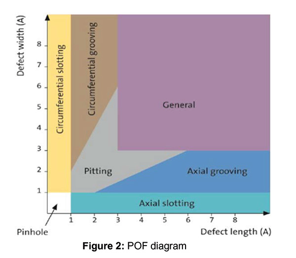
As discussed previously, SSWC mostly demonstrates a pattern of tight longitudinal metal loss that is centered on the longitudinal weld seam, usually within a larger area of light surface or general corrosion. SSWC tends to have a high length-to-width ratio and a V-shaped morphology.
When considering feature morphology for ILI purposes, SSWC is best described as axial slotting, as per the Pipeline Operators Forum (POF) categories for corrosion (Figure 2)7. With this in mind, it is important for any ILI system to be optimized for POD, POI and sizing for this feature category.
Measurement Principle
In API 1163 [6], an ILI System is defined as “[a]n inspection tool and the associated hardware, software, procedures, and personnel required for performing and interpreting the results of an ILI.” The key to the selection of appropriate ILI systems is to appreciate how the different elements of the system can be optimized to provide the best diagnostic data for target anomalies and features.
This involves not only understanding the anticipated tool dynamics associated with the pipeline’s specific properties, construction and operations but also how the different measurement principles and sensor technologies, combined with evaluation techniques, give the best opportunity to detect, identify and size the features.
As discussed, SSWC typically forms narrow V-shaped slots along the weld bond line. They may be quite short with very little overall volume of metal loss, and even when they are long, the volume change is small. This scenario is extremely challenging for the workhorse of the ILI business – a magnetic flux leakage measurement-based system where the flux is orientated axially to the pipeline (MFL-A). MFL-A tools are generally excellent for pitting and for small areas of general corrosion. The configuration is not ideal for narrow axially orientated features.
MFL technology relies on the on-board Hall effect sensor’s ability to detect magnet flux, which leaks or exits the pipe material because of a reduction in pipe wall thickness (typically metal loss caused by corrosion). Because SSWC is longitudinally oriented, the ideal would be to have the magnetic circuit circumferentially orientated (MFL-C) (Figure 3).
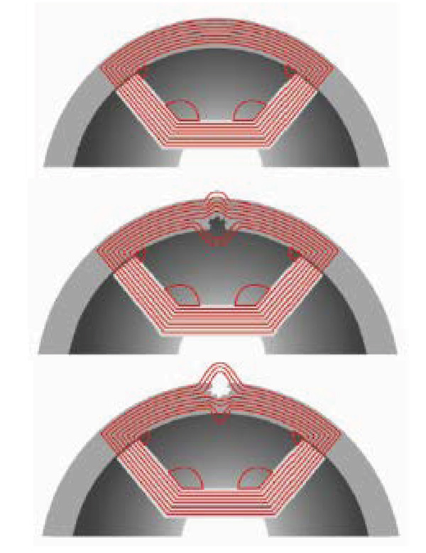
This is because MFL technology works best when the magnetic flux field is at 90° (perpendicular) to the primary orientation of the target features, maximizing flux leakage and the response from the sensors. MFL-C technology is designed specifically for the inspection of corrosion features that are predominately orientated in the longitudinal direction, i.e. axial slotting and grooving.
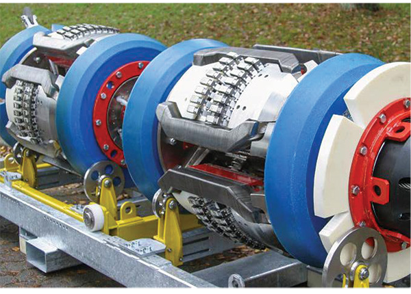
Understanding how the ILI system will respond to the pipe material, target defects and inspection conditions before an on-stream inspection is beneficial in vetting the evaluation strategy and procedure. This can be established using pull tests on features removed from service. While confirming an acceptable probability of detection (POD) is one of the primary objectives of pull tests, we also put an emphasis on establishing a “fingerprint” of the defect’s signal response for the ILI system.
By vetting these fingerprints, we have the opportunity to validate the sensor’s ability to detect the target feature and to ensure the resolution is of sufficient quality to establish a sound Probability of Identification (POI) (Figure 4).
Material Properties
In addition to selecting the most appropriate inspection system, having a sound understanding of the manufacturing process, material microstructure and mechanical properties (YS, UTS and Fracture Toughness) are primary requirements for evaluating SSWC, performing feature assessment and defining an appropriate response.
When information on material properties is limited, conservative assumptions are required. SSWC is more likely to be a problem experienced on vintage ERW and EFW pipe, which are also likely to have relatively poor properties – certainly compared to more modern ERW pipe. This influences the choice of appropriate response. Where SSWC is found to exist in association with poor properties (namely toughness and tensile properties in the weld zone), it will be very difficult to develop a response other than remediation.
If it can be established that the material properties are relatively good (i.e. toughness is moderate to high, and the weld zone is overmatched), then it may be possible to develop a response based on feature assessment and remaining life. It should be noted that this is very much dependent on defining a robust ILI capability for feature sizing and growth rate for SSWC, which can be difficult.
The industry guidance for appropriate SSWC growth rates is ambiguous, described as typically being two to four times the general corrosion rate in the pipe body8. Furthermore, if areas of corrosion are coincident with the longitudinal weld but are not SSWC, it is important to establish appropriate material properties if they are to be treated as a metal loss features using ASME B31.G.

SSWC Classification
For any pipeline suffering active external corrosion and where SSWC is credible, there will be cases of actual SSWC and cases where general corrosion is coincident with the long seam. Differentiating between these two cases is important for selecting an appropriate response.
Current integrity-management response and remediation requirements for any corrosion anomalies associated with the longitudinal seam weld would require some form of immediate or timed investigation. In an attempt to draw further value from the available ILI and material properties data, it is possible to assign a classification of “Likely,” “Possible” or “Unlikely” SSWC.
This is aligned with the guidance in API RP 1176, “Assessment and Management of Cracking in Pipelines” [9], for defining an appropriate response to ILI calls. Approaching the management of SSWC in this way allows operators to define a structured response for excavation activities to verify the process and remediate features as required.
By using likelihood classification, the risk to pipeline integrity can be reduced by acting on the most likely SSWC features as a priority while collecting the data needed to make informed decisions on where to focus resources and efforts to handle what is a very complicated and difficult-to-manage threat.
Management in Practice
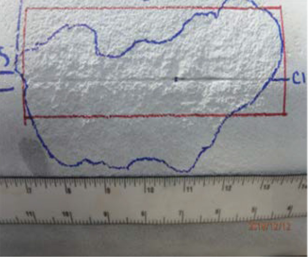
The above approach has been used to successfully differentiate between SSWC general corrosion crossing the longitudinal seam weld. The images in Figure 5 show an example of a “likely” SSWC feature that was positively confirmed as SSWC and an “unlikely” SSWC feature that was positively identified to not contain any selective or preferential component.
The SSWC feature requires remediation, and an appropriate response can be developed for the general corrosion. Battelle produced guidelines for assessing corrosion associated with the longitudinal weld10, 1, proposing that flow stress-based models, used to assess corrosion in the pipe body, can be applied to corrosion associated with the longitudinal weld, provided that, among other things, the material properties in the weld are characterized and equivalent to the pipe body.
Conclusion
Conventional responses to potential or identified threats have focused on in-situ investigations, often resulting in expensive and unplanned repairs for features reported by In-Line Inspection (ILI) that, when assessed, properly demonstrate a remnant life well into the next inspection interval. When ILI identifies metal loss indications co-located with the longitudinal seam weld, the current prescribed response is a blanket call for remediation. Such a response may not be appropriate if an ILI system is deployed to discriminate feature types, and integrity assessment is exercised leveraging a sound understanding of the pipe’s material properties.
Multiple ILI systems are now available to detect, identify and size anomalies associated with longitudinal seam welds, such as SSWC. By using an optimized approach to differentiate SSWC, appropriate response decisions can be made promoting risk reduction and using resources effectively.
References:
- Selective Seam Weld Corrosion Literature Review, Pipeline and Hazardous Materials Safety Administration, U.S. Department of Transportation, Report No.: ANEUS 811CSEAN120106, Rev. 2, November 11, 2012.
- Brossia, S., Selective Seam Weld Corrosion Literature Review, DNV Report to PHMSA, April 2012.
- Selective Seam Weld Corrosion Literature Review, Pipeline and Hazardous Materials Safety Administration, U.S. Department of Transportation, Report No.: ANEUS 811CSEAN120106, Rev. 2, November 11, 2012.
- Lukezich, S., Susceptibility of Modern ERW Pipe to Selective Weld Seam Corrosion in Wet Environments, Project PR-15-9306, Cat No: L51775, February 1998.
- Groeneveld, T.P., G.O. Davis and D.N. Williams, Susceptibility of Resistance Welded, Flash Welded, and Induction Welded Pipe to Selective Seam-Weld Corrosion, NG-18 Report No. 199, Pipeline Research Council International, 1991.
- ERW and Flash Seam Weld Failures, Battelle Final Report, J.F Kiefner and K. M Kolovich, September 2012.
- Specifications and requirements for in-line inspection of pipelines, Pipeline Operators Forum, version 2016.
- API1160 Managing System Integrity for Hazardous Liquid Pipelines, 2019.
- API1176 Recommended Practice for Assessment and the Management of Cracking in Pipelines, 2016.
- Leis B., Clark E., Zhu X., Galliher R., Guidelines for Assessing Corrosion Associated with Girth and Long Seam Welds, Battelle Final Report GRI-04/0119.
- Assessment of corrosion associated with the girth or long seam weld in vintage pipelines, EPRG project 177/2014, Ageing Pipelines Conference, 2015.
Author: Simon Slater is a principal integrity engineer working for ROSEN Integrity Services, based in Columbus, Ohio. Slater is a materials and welding engineer providing technical consultancy associated with structural integrity assessments, pipe material properties and welding engineering. He has been working for ROSEN Integrity Services for eight years. The majority of his time is focused on supporting the ROSEN UTCD and EMAT crack detection framework and the RoMat PGS pipeline material verification framework.

Comments