December 2021, Vol. 248, No. 12
Features
Advancing Design for Pipeline Slug Catchers
By Hooman Tabaraei, Process Specialty Engineer
Slug catchers are used at the terminus of large gas condensate transmission pipelines to catch large slugs of liquid, to hold these slugs temporarily, and to allow them to follow into downstream equipment and facilities at a rate at which the liquid can be properly handled.
It provides temporary storage for any surges (slugs) in liquid flows and roughly separates the gas from the liquids. These are vessel, manifold pipe, and parking loop (a combination of vessel and manifold pipe) types of slug catchers.
A pipe-type slug catcher consists of several long pieces of pipes, which together form the buffer volume to store the largest slugs expected from the upstream system. Vessel-type slug catchers can be used only if the incoming liquid volume is small, less than 629 bbl (100 cubic meters).
Both the separation and storage take place within the vessel, whereas separation and storage perform in separate, dedicated parts in finger and parking loop types.
Slug catchers are designed to dampen surges to a level that can be handled by downstream processing equipment to prevent overloading the system. The required size of a slug catcher is dependent on the liquid handling rate, pigging frequency and ramp-up rates.
The slug catcher is usually located directly at the upstream of the primary production separator, and the production separator volume is typically set by separation requirement rather than liquid surge capacity. Hence, priority is to capture the slug volume within a slug catcher.
The outlet gas is sent into the production separator to remove the entrained liquid. Nevertheless, while a slug catcher serves for a considerable separation to remove a production separator at the slug catcher downstream, the required gas space volume in addition to slug volume need to be investigated.
Vessel Type
A vessel-type slug catcher consists of two sections for gas-liquid separation and liquid storage. The separation section can be sized according to either k-value or settling law methods, and the storage section is designed to accommodate the slug volume plus buffer volume between low liquid level (LLL) and high liquid level (HLL).
For vertical vessels, the storage section between the vessel bottom tangent line (T/L) and HLL is designed so that the volume between HLL and LLL equals the slug volume plus buffer volume, and the geometrical volume between LLL and the bottom T/L covers the total inlet liquid flowrate multiplied by retention time between LLL and T/L.
For a horizontal vessel, the storage section between the vessel bottom T/L and HLL is designed to accommodate the total slug volume plus buffer volume, along with the volume liquid flowrate multiplied by retention time.
The geometrical volume between HLL and the vessel bottom T/L can be computed as partial volume of the vessel, excluding heads, plus partial volume of heads.
- Separation section
- k-value method
For a vertical position, the terminal velocity is assumed to be the same as the maximum superficial gas velocity. Hence, Dmin (minimum vessel inside diameter) =
Where Vg,max (superficial gas velocity within vessel) =
K
For a horizontal position, the gas velocity (QG / AG) in the gas space should not exceed the maximum superficial gas velocity, so there is sufficient time for the liquid droplet to leave the gas phase and move into the liquid section. AG (gas space cross-sectional area above HLL within the vessel) = AT (total cross-sectional area) - A (partial cross-sectional area).
- Settling Law
For a vertical orientation, the terminal velocity is assumed to be the same as superficial gas velocity. Hence, Dmin (minimum vessel inside diameter) =
Where Vg,max can be acquired according to the following relations for Vterminal, depending on the specified liquid particle diameter entrained at the gas outlet flow.
Newton’s Law
Intermediate Law
Stokes’ Law
If the desired liquid particle diameter entrained at the outlet gas from the slug catcher is less than the calculated particle diameter according to Stokes’ law (Re < 1), then the settling velocity can be determined per Stokes’ law. If the specified particle diameter is less than the calculated particle diameter according to intermediate law (1 < Re < 1,000), the settling velocity can be calculated according to intermediate law; otherwise, it estimates according to Newton’s law.
For a horizontal orientation, the settling time of liquid particles should be equal to or less than the movement time of the liquid particle over the length of the vessel to provide an efficient gas-liquid separation within the gas space. Hence, HLL/settling velocity of liquid (Vt) ≤ vessel length (L) / gas velocity (VG).
To size a vessel-type slug catcher in a vertical position, one must first figure out the minimum inside diameter of the vessel according to either settling velocity or k-value method. Then increasing the calculated vessel inside diameter, if required to accommodate the total slug volume plus buffer volume within the vessel between LLL and HLL, the defined gas space volume ratio must be considered.
In other words, the HLL within the vessel, estimated according to the initial calculated vessel inside diameter, accommodates the slug volume plus buffer volume between HLL and LLL, then the gas space height can be determined as the vessel inside diameter x L/D – calculated HLL. If it is less than the specified gas volume ratio above HLL, the calculated vessel inside diameter increases so that the calculated available gas space height above HLL becomes equal to or more than the specified gas space height.
For a vessel-type slug catcher at a horizontal orientation, to accommodate the summation of inlet slug volume and buffer volume, an initial vessel inside diameter, along with the liquid volume between the vessel bottom T/L and LLL, must be determined. Then, the initial calculated vessel inside diameter increases so that the gas space cross-sectional area above the HLL becomes equal to or larger than the gas volume rate (m3/s)/gas superficial velocity(m/s), if the k-value is selected as the separation method.
Otherwise, the settling time of the liquid droplet should be equal to or less than the liquid droplet movement over the slug catcher vessel length, i.e., HLL/Vt ≤ L/VG
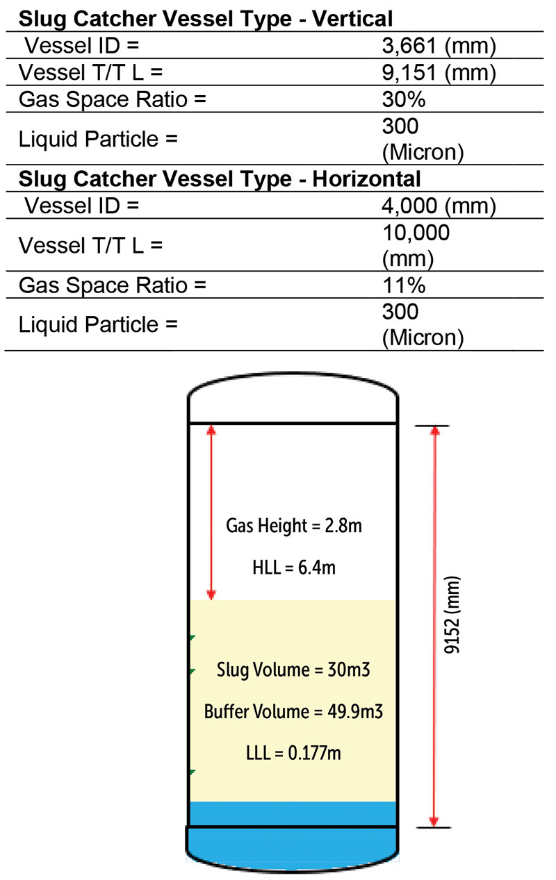
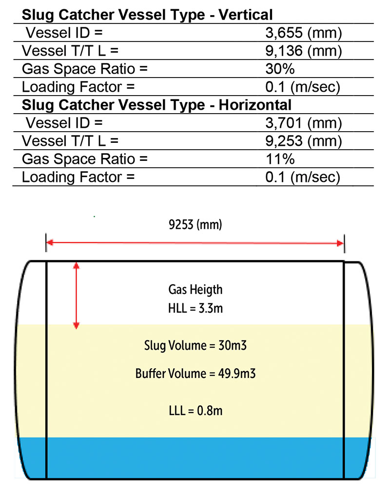
Example: Design of slug catcher vessel type based on inlet maximum possible liquid slug or surge 30 m3, buffer volume 50 m3, inlet gas mass flowrate 90,000 kg/h, inlet gas mass density 65 kg/m3, inlet gas viscosity 0.01 cp, inlet oil mass flowrate 195,800 kg/h , inlet oil density 710 kg/m3, inlet water mass flowrate 25,200 kg/h and inlet water density 1,076 kg/m3, whereas the required maximum particle diameter of entrained liquid in gas outlet flow as 300 micron, vessel L/D = 2.5, and 3 min retention time between vessel bottom T/L and LLL.
The calculated dimensions of slug catcher vessel type in either vertical or horizontal positions according to the input data are as follows:
Parking Loop Type
A parking-loop-type slug catcher consists of two disconnected sections of gas-liquid separation and liquid storage. The separation section can be sized according to either k-value or settling law methods, and the storage section is designed to accommodate the slug volume plus buffer volume in a long single pipe loop outlet from the separator.
n Storage section
The parking loop is designed to accommodate the slug volume plus buffer volume. Parking loop is a long single pipe loop outlet from the separator vessel.
Parking Loop Volume (Vslug+buffer) =
πⅆ2 Ls Nl4
4
where d = pipe inside diameter (m)
Ls = straight length per pass (m)
Nl = pass number
VS+B = slug volume (m3) + buffer volume (m3)
Hence, the number of pass (Nl) =
4 (Slug Volume + Buffer Volume)
πⅆ2 Ls
Separation Section
Design principles of the separation section of the parking-loop-type slug catcher are similar to the aforementioned vessel type. The vessel inside diameter in vertical position is determined according to either k-value or settling laws. Then, the HLL within the vessel determines the calculated vessel inside diameter and defined retention time between HLL and vessel bottom T/L.
To size a parking-loop-type slug catcher, consisting of a vertical vessel, one must first figure out the vessel inside diameter. Then, it will increase, if required to accommodate the liquid volume between the vessel bottom T/L and HLL according to the defined retention time, by considering the gas space volume ratio.
The pass number of the storage loop is determined by total slug volume plus buffer volume, length of the plot of slug catcher and selected pipe inside diameter.
Example: Design of slug catcher parking loop type based on inlet max possible liquid slug or surge 30m3, buffer volume 50m3, inlet gas mass flowrate 90000kg/h, inlet gas mass density 65kg/m3, inlet gas viscosity 0.01cp, inlet oil mass flowrate 195800kg/h, inlet oil density 710kg/m3, inlet water mass flowrate 25200kg/h and inlet water density 1076kg/m3, whereas the required maximum particle diameter of entrained liquid in gas outlet flow as 300micron, vessel L/D = 2.5, and 3min retention time between vessel bottom T/L and HLL.
The calculated dimensions of a parking-loop-type slug catcher in either vertical or horizontal positions according to the input data are as following:
In addition to the separation section results shown on above, the storage consists of the pipeline loop length of 50 meters, a nominal 20-inch inside diameter, and nine pass numbers to accommodate the total slug volume plus the buffer volume.
Finger Type
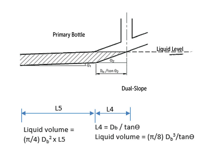
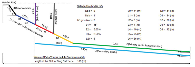
The general configuration consists of the fingers with dual slope and three distinct sections of gas-liquid separation, intermediate and storage. Gas risers are connected to each finger at the transition zone between the separation and intermediate sections. Gas equalization lines are located on each finger. These lines are located within the slug storage section. Liquid header collecting liquid from each finger. This header will not be sloped and is configured perpendicular to the fingers.
Finger-type slug catchers are usually less expensive than vessel-type slug catchers of the same capacity due to thinner wall requirements of smaller pipe diameters. The manifold nature of multiple pipe-type slug catchers also makes possible the later addition of additional capacity by laying more parallel pipes.
Since the pipe-type slug catcher is defined as a piping configuration rather than a pressure vessel, it is not constrained to the same requirements as a normal vessel.
The length of each part of a slug catcher is determined as follows:
- L0 (Inlet pipe) = 10 x pipe inside diameter
- L1 (Downcomer length) = gas riser height / SinƟ1
- The downcomer inlet nozzle and the gas riser outlet nozzle are assumed at the same elevation above grade.
- L2 (gas/liquid separation length between downcomer outlet nozzle and the first gas riser take-off) = η x 4 x settling time x QG/ (π Db2 x Npb)
- (Db= primary bottle inside diameter; Npb = Number of primary bottles; QG = Total gas flowrate. Settling time estimates determined by settling laws depends on specified liquid particle diameter; η = gas separation efficiency)
The length of the primary bottle between its entry and gas outlet riser is determined by the desired settling and separation efficiency. If the desired liquid particle diameter carried over into the outlet gas from a slug catcher is less than the calculated particle diameter according to Stokes’ law (Re < 1), then the settling velocity can be determined according to Stokes’ law. If the specified particle diameter is less than the calculated particle diameter as per intermediate law (1 < Re < 1,000), settling velocity is calculated using intermediate law; otherwise, it is estimated using Newton’s law. After estimating the settling velocity (Vt), the settling time is calculated as Db/Vt.
Gas/liquid separation through primary bottle pipes occur when the settling time becomes equal with separation time, i.e., L/VG, where VG = QG/A. Hence, L/VG = Db/Vt. Hence, L = (Db/Vt) x VG, VG = QG/AG = η QG/(π Db2 Npb / 4).
Settling velocity by considering swarm is corrected as Vt, Swarm = Vt (1-H)n and ranges from 4.65 to 2.39 for 0.1 ≤ Re ≤ 500. H is liquid hold-up fraction can range up to 0.2
L3 (gas/liquid separation length between risers) = (1-η) x 4 x settling time x QG / (π Db2 x Npb)
L4 (intermediate section length) = (Db / tanƟ) / CosƟ
L5 (primary bottle length) = total available length of SC plot - (L0 + L1 Cos Ɵ1 +
L2 CosƟ2 + L3 CosƟ2 + L4), in case of single slope L4 = 0
L6 (secondary bottle length) = L3 + L4 + L5
The selected inside diameter of the inlet pipe, header, downcomer and primary bottle sections should be large enough to form a stratified smooth flow regime in which separation happens.
The geometry volume of each part of slug catcher is determined as follows:
- V1(storage volume of primary bottles between riser and liquid outlet) = Npb x (π/8) Db3/ tanƟ for single slope design and Npb x ((π/4) Db2 L5 + (π/8) Db3 / tanƟ) for dual slope design
- V2(storage volume of secondary bottles) = Nsb x ((π/8) Db3/ tanƟ + (L6 – Db/SinƟ) (π/4) Db2 ) for single slope design and Nsb x L6 (π/4) Db2 for dual slope design
- V3(storage volume of liquid outlet header) = (π/4) Dh2 x Lh (Dh = inside diameter of outlet liquid header; Lh = length of outlet liquid header ≥ (Npb x primary bottle outside diameter + Nsb x decondary bottle outside diameter)
The geometrical volume of the storage portion of a slug catcher should accommodate the max possible slug volume from a two-phase inlet pipeline at any moment plus the buffer volume of condensate to guarantee the liquid supply to facilities located at downstream of the slug catcher. Hence, an optimized design of a slug catcher can be achieved by selecting a proper Nsb by trial and error, so that V1 + V2 + V3 ≥ Vslug + Vbuffer.
The gas riser inside diameter can be determined so that no liquid carry-over occurs when the large liquid volumes of slug arrive in the slug catcher. The separation capability of the riser is determined as per equation VSG ≤ K ((ρL – ρG)/ ρG)0.5
where K is load factor (m/sec) and VSG (superficial gas velocity via gas riser) = (1+ η) x (QG / Npb) / (Nriser π/4 Driser2)
η = over design margin on gas flowrate due to mal-distribution, Nriser = number of gas risers, and Driser = gas riser inside diameter.
Hence, Driser = ((1+η) QG / (Npb x Nriser x (π/4) K ((ρL – ρG)/ ρG)0.5 ))0.5.
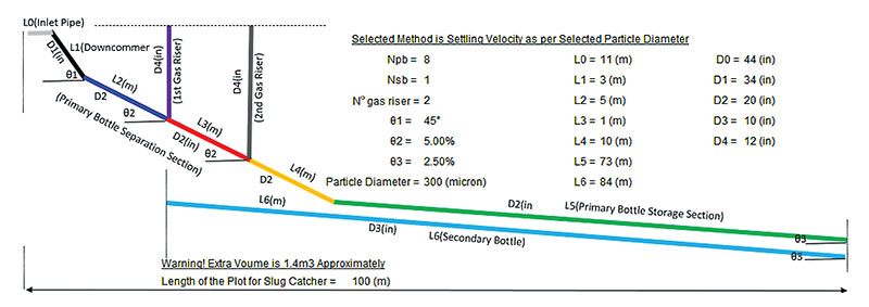
Example: Design of slug catcher finger type based on inlet max possible liquid slug or surge 70m3, buffer volume 50m3, inlet gas mass flowrate 90000kg/h, inlet gas mass density 65kg/m3, inlet gas viscosity 0.01cp, inlet oil mass flowrate 195800kg/h, inlet oil density 710kg/m3, inlet water mass flowrate 25200kg/h and inlet water density 1076kg/m3, whereas the required maximum particle diameter of entrained liquid in gas outlet flow as 300micron, and the available length of the plot of slug catcher is 100m.
The calculated dimensions of a finger-type slug catcher according to the input data are as follows:
The computed dimensions using L/D = five method rather than 300-micron liquid droplet scenario, will result as follows:
Author: Hooman Tabaraei is a U.K.-based process engineer working for a global engineering and construction company. He has experience in petroleum refining, petrochemicals and offshore oil and gas platforms. He holds a bachelor’s degree in chemical engineering from the University of Tehran.





Comments