
May 2022, Vol. 249, No. 5
Features
27-Day ILI Run: A Case Study of a Low-Pressure, Low-Flow Gathering Line
By Denise M. Earles, P.E., and Peter Van Beugen Pipesurvey USA, an INVACOR Partner Company, and Pipesurvey International
In 2011, a customer, who was in a difficult situation, approached Pipesurvey International (PSI). The customer had a pipeline that ran from the Q1 Field in the North Sea 52 miles (81 km) off the coast of The Netherlands, to an offshore terminal that needed an in-line inspection (ILI).
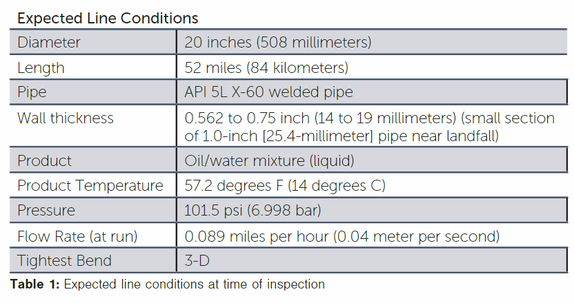
Unfortunately, the Q1 Field was at the end of its life, resulting in very little production with no feasible method to boost the flow rate. The resulting run conditions (Table 1) made an ILI run exceptionally difficult.
However, the regulatory authority, Staatstoezict op de Mijinen (SODM, translated as The Dutch State Supervision of Mines) required that the pipeline be inspected.
Design Considerations
The line had been inspected 10 years prior, using an ultrasonic tool with mixed results. There was paraffin in the line that had built up on the ultrasonic tool interfering with the tool’s ability to accurately attenuate sound waves.
The resulting inspection yielded good data at the beginning of the line, but degraded in quality as the tool progressed, yielding no data in the last section. Based on this history, it was known that a cleaning regimen would be a key component of a successful project. In need of inspection data for the full line to meet regulatory requirements, the customer was in search of a different inspection methodology.
Magnetic flux leakage (MFL) technology is a good option for visualizing metal loss, and when paired with a caliper inspection for deformations, provides a good understanding of the current state of the pipeline. While dirt and debris can interfere with any type of ILI inspection, MFL is much less sensitive to the cleanliness of the pipeline.
Ultimately, this technology combination was chosen. Both chemical and mechanical pre-cleaning options were evaluated. In consultation with the customer, a mechanical cleaning option was chosen. Because of the long run-time, there would only be one opportunity to run a mechanical cleaning tool. If the cleaning was too mild, the MFL tool would not be able to yield good data. However, if the cleaning was too aggressive, paraffin could accumulate in places in the line that would cause the tool to stick and stop moving.
PSI, never one to turn away from a challenge, started investigating tool modifications to make the ILI inspection successful. Because of the additional magnetic forces against the pipe wall inherent in an MFL tool, the MFL tool presented more challenges than either a caliper or mechanical cleaning tool.
It was decided that the MFL tool would be the focus of the investigation. Once modifications proved successful for the MFL tool, they would be applied to the caliper and cleaning tools to enhance their performance.
The PSI standard MFL tool is a magnetic bar (mag-bar)-based design. This is generally a lower-friction design when compared to a brush-based MFL tool. It also means that in the case of any debris in the pipeline, the tool is riding or “skiing” on top of the debris, rather than trying to push the debris in front of it, similar to a broom.
The PSI tool also features a wheel-based yoke. This means that the tool rides along the pipe wall on these wheels, located on either side of the mag-bars (Figure 1).
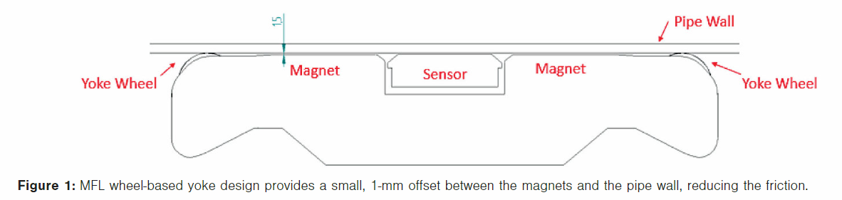
The magnets themselves are designed to be offset from the pipe wall, further reducing the friction to be overcome.
This typically means that the PSI MFL tool has lower line pack and pressure differential requirements than the majority of the tools on the market, giving PSI a head start in solving the customer’s dilemma.
While the PSI MFL tool offered inherent benefits for the application, modifications were still required. Based on the line conditions shown in Table 1, the run time was calculated to be 584.2 hours, or 24.3 days.
Finding adequate batteries to safely keep the tool’s electronics running this long would be a challenge. The first line of attack was to reduce the energy requirements of the tool. After discussing with the customer, it was decided that the fiber optic inertial measurement unit (IMU) integrated into the MFL tool would not be feasible on this run.
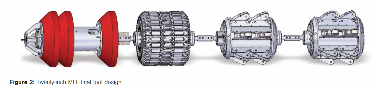
So, the inertial measurement unit (IMU), located in the first module (Figure 2) was replaced with a gyroscope, allowing identified defects to be accurately located on the pipe wall (o’clock position) but using significantly less power than the IMU.
Along the same lines, because the tool was expected to be traveling through the pipeline so slowly, the sample frequency of the tool could be greatly reduced to only 20 Hz. This lower frequency still resulted in a sample distance of 1.8 mm along the length of the pipeline.
Once the power needs were reduced, the next thing to focus on was the packaging and actual design of the batteries and battery modules. PSI engaged directly with the battery manufacturer, using their expertise to design and test the battery packaging.
A standard 20-inch PSI MFL tool has two modules. The first module houses all the electronics, batteries, and IMU, and the rear module contains the magnets and sensors. This was just not enough space to fit the additional batteries required.
Two additional battery modules were added to the rear of the tool (Figure 3). When it came to the single module caliper tool, which has much lower power consumption than the MFL tool, additional batteries could be accommodated without lengthening the tool.
In parallel, PSI turned their attention to safety considerations. With lithium-ion batteries, rapid discharge is a serious concern, and the extraordinary run time required in this application only served to heighten the concern. PSI conducted deep discharge testing, testing the batteries through a full 255-hour cycle monitoring the temperature and discharge cycle of the batteries. Also, as an additional safety precaution, a second fuse was added to the printed circuit board to guard against rapid discharge in the line.
When designing an MFL tool, the sizing models are developed based on a certain range of magnetic saturation of the pipe wall. When a tool moves too quickly through the pipeline and is unable to fully magnetize the pipe wall as it passes, there is usually a concern about undersaturation of the pipe wall. Without proper saturation levels, sizing models can be inaccurate.

In this case, however, the MFL tool would be moving slowly, risking the opposite phenomenon, oversaturation of the pipe wall. Fortunately, this oversaturation was largely canceled out by the relatively heavy wall thickness of the line. Testing for oversaturation was performed using a pull test rig. The MFL tool was pulled at the expected run speed via mechanical winch through heavy wall pipe spools with known machined defects.
During the test, the magnetization levels of the pipe spools were measured to ensure oversaturation did not occur. Data collected by the tool during the test were then used to calibrate the analysis software and confirm accurate results.
Data storage also required modification due to the length of the pipeline. The PSI caliper and MFL tools are unique in that they record both distance-based data (with an odometer system) and time-based data (utilizing elapsed time from the tool being activated). To record both sets of data for such a long time, the usual memory cards would not suffice. The memory cards were upgraded to hold a larger amount of memory, as well as adding additional memory cards to the tools.
The remaining modifications were centered around keeping the tool moving in the line, further reducing friction and bypass in the tools. The first change was to reduce the number of cups.
Figure 2 shows the two battery modules (located at the rear of the MFL tool) were mounted on wheels instead of the standard bypass cups. This not only reduces the friction but ensures that all the back pressure acts on the front module drive cups. The drive cups were also redesigned to be a continuous smooth profile, ensuring a good seal with no bypass as well as using a softer urethane material to make the drive cups more flexible. Lastly, the tool needed to be “sealed up.”
Some bypass always occurs through bolt holes, etc., in the modules of the tool and is typically not an issue. In this very low-pressure low-flow environment, it was crucial that all the pressure act directly on the drive cups to keep the tool moving in the line. So, every bolt on the tool was outfitted with Teflon washers to prevent even minimal bypass. These changes were applied not only to the MFL tool but the caliper and mechanical cleaning tool as well.
Field Operations
Feasibility and preliminary design work were performed and discussed with the client prior to the order. PSI received the purchase order on Nov. 18, 2011, and field work began approximately 2-1/2 months later, on Feb. 5, 2012. All three runs (cleaning, caliper, and MFL) were completed by May 5 of the same year.
The cleaning tool was launched first, successfully traversing the line and bringing in several barrels of wax. Next, the caliper tool was vertically launched (Figure 3) and received into the trap without incident.
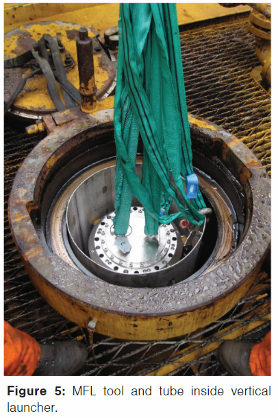
Lastly, the MFL tool was run. To vertically launch the MFL tool, it was inserted and locked into position in a tube. This tube was then lifted by a crane (Figure 4) and inserted into the vertical launcher (Figure 5). The MFL tool was then released from the tube. The tube was removed prior to launch.
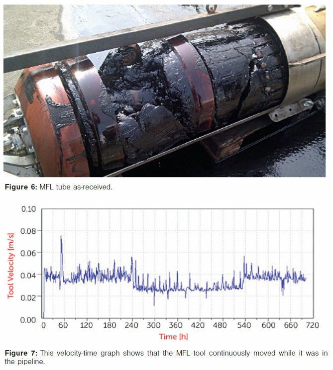
The MFL was received 27 days, 2 hours, and 23 minutes after it was launched. Upon initial removal from the receiver, it was obvious that the tool picked up paraffin in the line despite the prior cleaning run (Figure 6). Upon downloading the data, however, it became clear that the right balance of cleaning had been achieved. The odometers measured 52.6 miles (84.7 km), and most importantly, the inspection had less than 0.1% data loss.
The velocity-time graph (Figure 7) shows that the tool did not stop in the line, achieving continuous measurement for the full 27 days of the run.
Future Applications
In November 2021, the Pipeline Hazardous Materials Safety Administration (PHMSA) issued document 86 FR 63266 “Pipeline Safety: Safety of Gas Gathering Pipelines: Extensions of Reporting Requirements, Regulations of Large, High-pressure Lines, and other Related Amendments,” known largely in the industry as “The Mega Rule.”
In this rule, PHMSA modified the definition of regulated pipelines, requiring that an additional 425,000 miles (684,000 kilometers) of onshore gas gathering lines that were previously unregulated (PHMSA 2021) would now be regulated. These gas gathering lines run from product facilities to the large-diameter, cross-continent transmission lines. They are typically smaller-diameter lines that operate at low pressures and low flow rates.
Most ILI tools currently on the market are designed to operate in previously regulated higher-pressure (+~500 psi [34.5 bar]) pipelines. Reducing the operating pressures of these tools is especially difficult in pipelines that carry compressible gases, such a natural gas.
Many of the newly regulated gathering lines have pressures as low as 80 or 100 psi (5.5 to 6.8 bar), which often results in speed excursions during an ILI run. When an ILI tool stops in a compressible gas line, the pressure builds up behind the tool until the force is great enough to overcome the initial momentum of the stopped tool.
Finally, when the pressure is sufficient to move the tool, the gas rapidly decompresses, causing the tool to suddenly move at a very high speed, sometimes greater than 70 miles per hour (31 meters per second). Since the pipeline is at a lower pressure line pack, it has insufficient pressure in front of the tool to help counteract or slow down the quick movement.
At this point, the tool rapidly moves down the pipeline then slows as the pressure reduces back to line pressure. The tool will then traverse unless the friction forces exceed the propelling force of the line pressure resulting in the tool, once again stopping in the line. The phenomenon of surge-stop repeats itself down the length of the line, resulting in poor quality and missing data (due to the inability to fully saturate the pipe wall at high speeds), as well as damage to the tool from high-speed collisions in bends, etc.
The Q1 Field project has given PSI, and their partner Pipesurvey USA, an INVACOR Partner Company (PSUSA), the real-world experience necessary to design tools to overcome the challenges faced in inspecting gathering lines.
In addition to the standard PSI tool of accurately sizing at speeds up to 10 mph (4.5 meters per second), the lessons learned modifying tools to reduce friction, reduce bypass, and optimize lithium-ion batteries are all directly transferable. Prototype tools are currently being built and tested in anticipation of the PHMSA Mega Rule, taking effect May 16, 2022.
References:
- Ministry of Economic Affairs. 2006. Oil and Gas in the Netherlands Exploration and Production 2005 and Prognoses 2006-2015, revised version August 2006
- PHMSA 86 FR 63266. Pipeline Safety: Safety of Gas Gathering Pipelines: Extensions of Reporting Requirements, Regulations of Large, High-pressure Lines, and other Related Amendments (2011)
- PHMSA. 2021, November 15. New Federal Regulations Add More Than 400,000 Miles of “Gas Gathering” Pipelines Under Federal Oversite [Press Release]. Retrieved from https://www.phmsa.dot.gov/news/new-federal-regulations-add-more-400000-miles-gas-gathering-pipelines-under-federal-oversight
Editor’s note: Presented at the 34th Pipeline Pigging & Integrity Management Conference, Jan. 31-Feb. 4, 2022. © Clarion Technical Conferences and Great Southern Press. Used with permission.

Comments